PCB for 1590BB enclosure (horizontal)
This board simplifies building your DIY guitar pedal in a 1590BB enclosure. With the LEDs, jacks, and footswitches mounted directly to the board, you only need to wire the battery and the effect PCB.Steps
Categories
Status: Active

Wiring Step 4 of 12
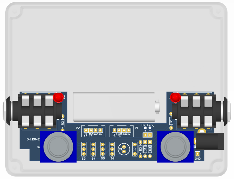
The PCB is designed to be mounted in a 1590BB enclosure as shown below. Refer to the drilling template for the exact hole coordinates.
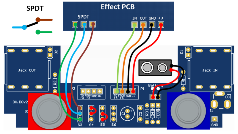
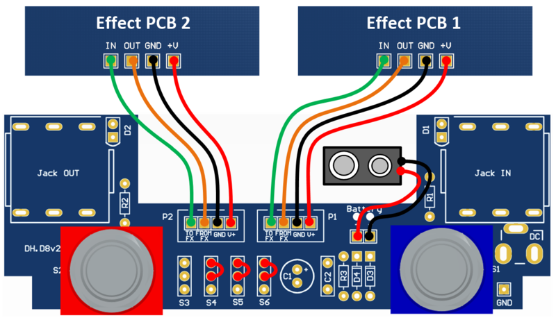
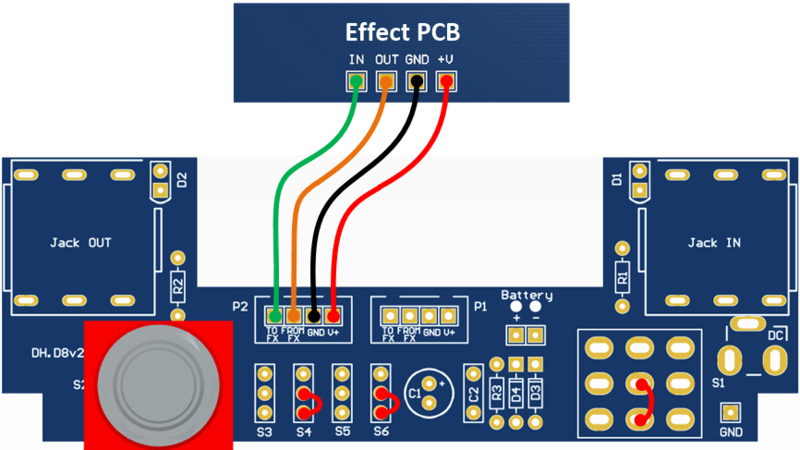
To connect the 1590BB PCB to the effect PCB, use an XH 4-pin male connector on the 1590BB board and an XH 4-pin female connector with wires soldered to the effect PCB. Alternatively, you can solder the wires directly, as shown in the figure below.
The PCB pins are labeled as "GND", "+V", "FROM FX", and "TO FX". Connect the "FROM FX" pin to the output of the effect PCB and the "TO FX" pin to the input of the effect PCB.
SWITCHING CONFIGURATIONS
The PCB supports several switching configurations:
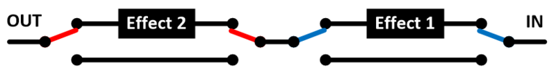
Individual Effects: The right and left footswitches independently control their respective effects.
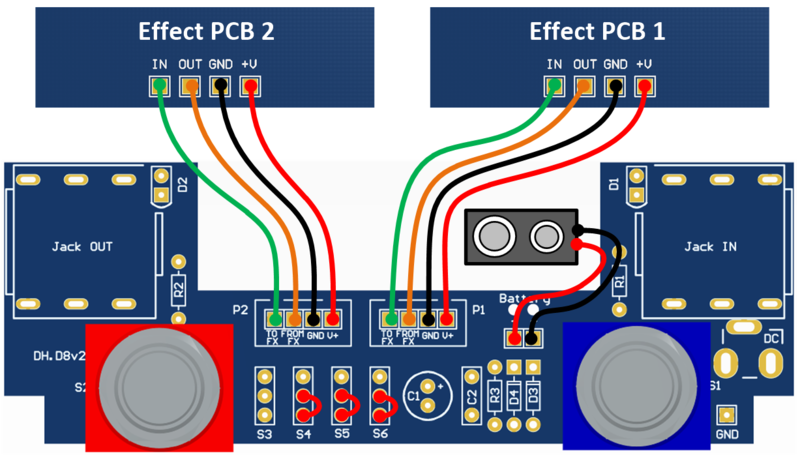
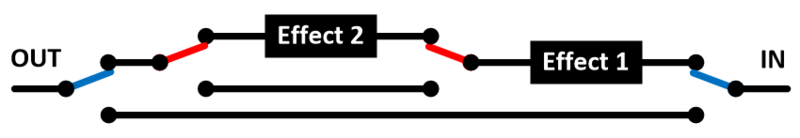
Nested Effects: The right footswitch controls the overall bypass. The left effect is only active when the right footswitch is engaged. This is ideal for using a boost after an overdrive or distortion pedal.
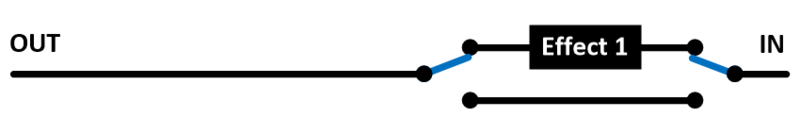
Single Effect (Right Footswitch): Use this configuration for a single effect unit in a 1590BB enclosure, with control on the right side.
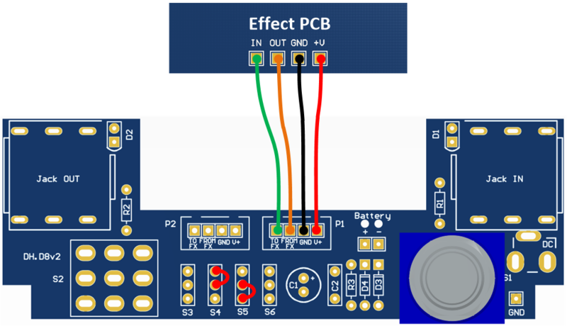
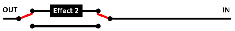
Single Effect (Left Footswitch): Use this configuration for a single effect unit in a 1590BB enclosure, with control on the left side.
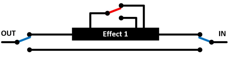
Single Effect with SPDT Switch: The right footswitch bypasses the effect, while the left footswitch controls a SPDT switch. This is perfect for switching between diodes, different tones, or a boost.