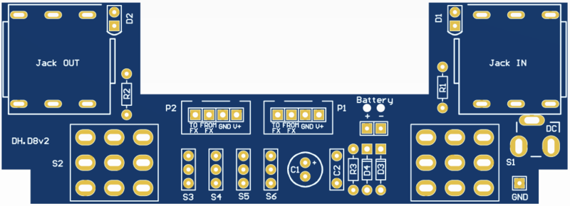
PCB for 1590BB enclosure (horizontal)
This board simplifies building your DIY guitar pedal in a 1590BB enclosure. With the LEDs, jacks, and footswitches mounted directly to the board, you only need to wire the battery and the effect PCB.Steps
Categories
Status: Active

Designators and components Step 2 of 12
COMPONENT LIST
PCB 1590BB DIY PCB GUITAR EFFECT
C1 100u 100UF 35V 105C RADIAL ELECTROLYTIC CAPACITOR 6X11MM
C2 100n 100NF 0.1UF 100V 5% POLYESTER FILM BOX TYPE CAPACITOR
D1 Led LED 3MM GREEN
D2 Led LED 3MM GREEN
D3 Jumper (Optional 1N4001 DIODE 1A 50V)
D4 1N4001 1N4001 DIODE 1A 50V
R1 3.3k 3.3K OHM 1/4W 1% METAL FILM RESISTOR
R2 3.3k 3.3K OHM 1/4W 1% METAL FILM RESISTOR
R3 47 47 OHM 1/4W 1% METAL FILM RESISTOR
DC Jack DC POWER JACK 2.1MM BARREL-TYPE PCB MOUNT
JACK IN 6.35MM 1/4" STEREO INSULATED SWITCHED SOCKET JACK PCB
JACK OUT 6.35MM 1/4" STEREO INSULATED SWITCHED SOCKET JACK PCB
S1 3PDT 3PDT STOMP FOOT / PEDAL SWITCH
S2 3PDT 3PDT STOMP FOOT / PEDAL SWITCH
BATTERY 9V 9-VOLT BATTERY CLIP / CONNECTOR SNAP
CONNECTOR XH 4-PIN MALE CONNECTOR
PCB
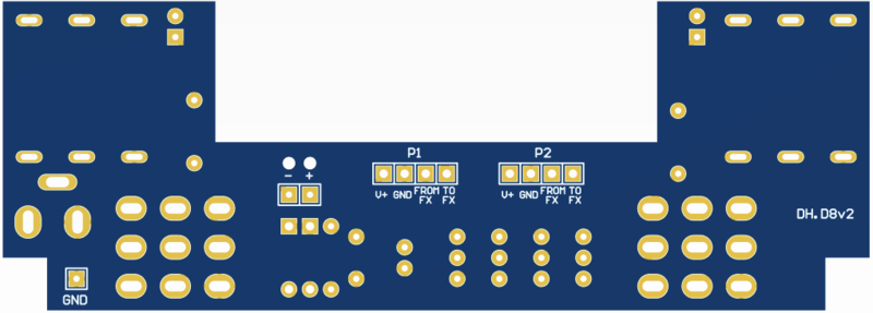
PCB SCHEMATIC
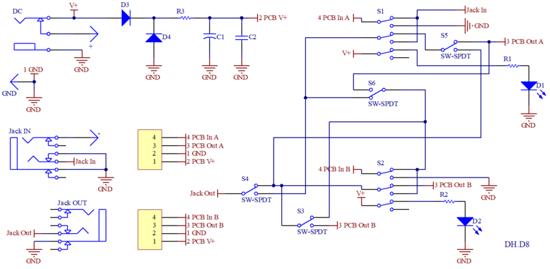
CIRCUIT DESCRIPTION
Diode LED
Resistors R1 and R2 act as a current limiter for the LEDs. Select the resistance value to achieve the desired brightness. A range of 2.2kΩ to 4.7kΩ is recommended for standard LEDs.
Noise filter
Capacitors C1 and C2, paired with R3, filter noise from the power supply. To bypass this filter, omit C1 and C2 and replace R3 with a jumper.
R3 will drop the voltage reaching the effect PCB. Replacing R3 with a jumper will maintain the full power supply voltage, but with a less effitive noise filtering.
Reverse polarity protection
Diodes D3 and D4 provide reverse polarity protection. You can use D3 (for series protection) or D4 (for parallel protection), or both simultaneously.
- Series Protection (D3): Provides reliable protection by blocking current flow, but with a voltage drop (approximately 0.6V for the 1N4001 diode).
- Parallel Protection (D4): Has no voltage drop under normal operation. However, if the polarity is reversed, the diode can be damaged, potentially leading to component failure and requiring replacement.
If your effect PCB already has reverse polarity protection, you can omit D3 and replace D4 with a jumper.