Arduino PID Controller Shield
This easy-to-make shield converts your Arduino into a full-featured PID controller.Steps
Categories
Status: Active

Create probes Step 9 of 15
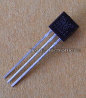
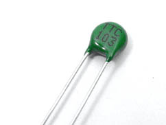
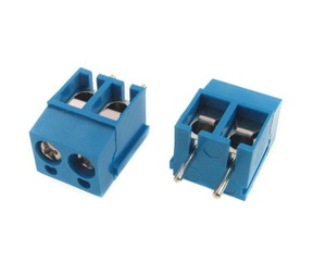
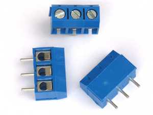
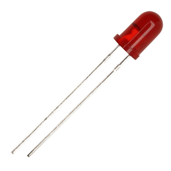
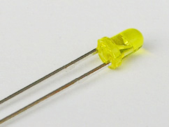
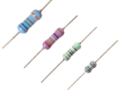
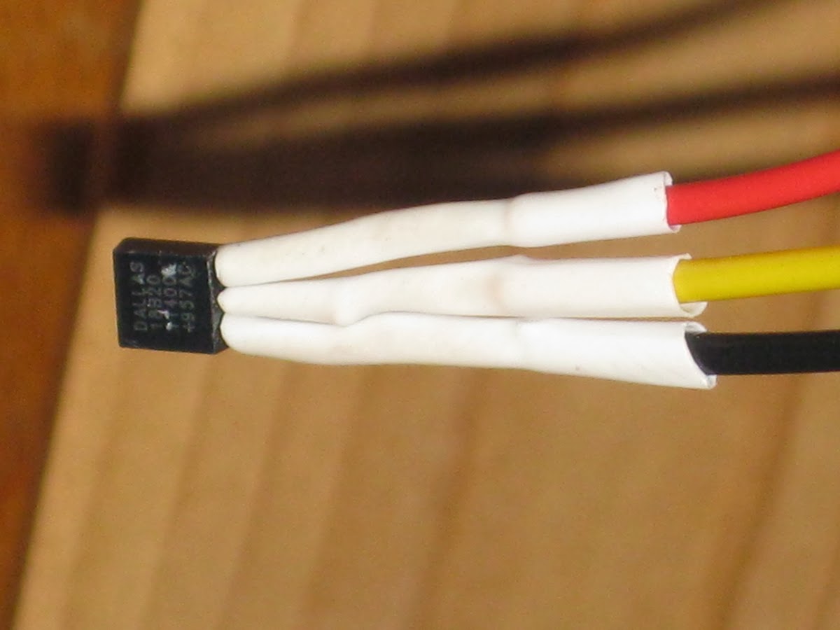
Now make the temperature probes. Solder red and black stranded wires to the thermistor pins. (These can be twisted if desired to reduce noise on the input). Solder red, black, and yellow stranded wires to the DS18B20 VDD, GND, and DATA pins, respectively. Insert the chosen temperature probe into the appropriate terminals of the 3-position input terminal block. The thermistor goes between VDD and DATA, forming a voltage divider with a 10 KΩ 1% resistor whose legs are clamped in DATA and GND. (Select the reference resistor that measures 10 KΩ most exactly on your multimeter.) Alternatively, connect all 3 wires from the DS18B20 to the appropriate terminals, and a 4.7 KΩ resistor between DATA and VDD acting as a pull-up on the DATA line. It's a good idea to insulate the legs of the probe with heat shrink or electrical tape. And if the temperature probe is going to go somewhere wet, it is probably advisable to put it in some kind of thermowell. For a visual indication of the output, we can clamp the legs of a LED in the terminals of the 2-way output block.
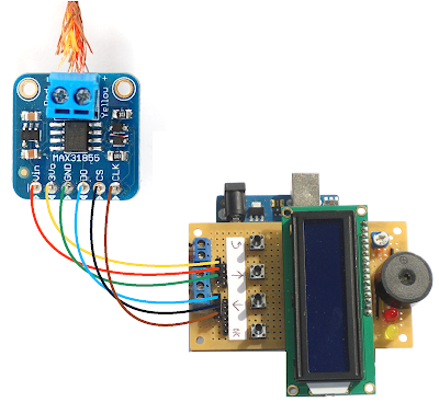
The picture below shows how to connect an Adafruit MAX31855 breakout board to the stripboard Arduino PID shield. Vin should connect to the 5V pin and DO, CS, and CLK to A0, A1, and A2 respectively. Connect a K thermocouple in the screw terminals. If the temperature reading goes down when it should go up, switch the thermocouple wires around. (NB. The MAX31855 breakout board and thermocouple must be bought separately.)