Arduino PID Controller Shield
This easy-to-make shield converts your Arduino into a full-featured PID controller.Steps
Categories
Created by Magic Smoke
Status: Active
Status: Active

Add components Step 7 of 15
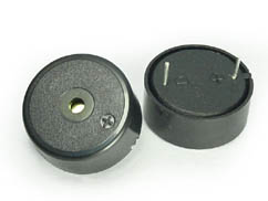
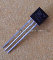
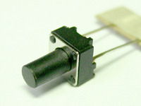
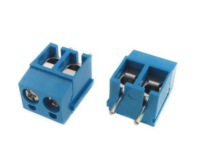
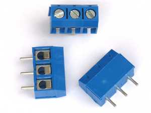
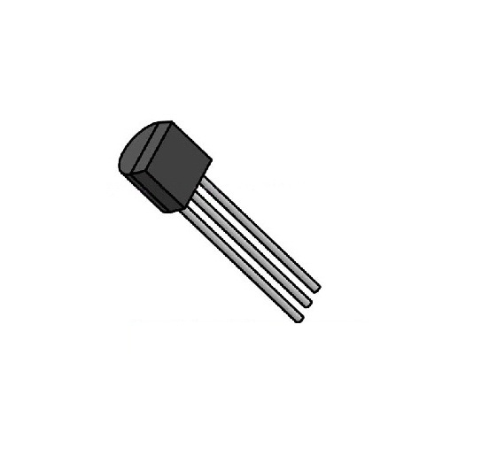
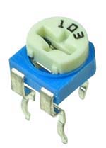
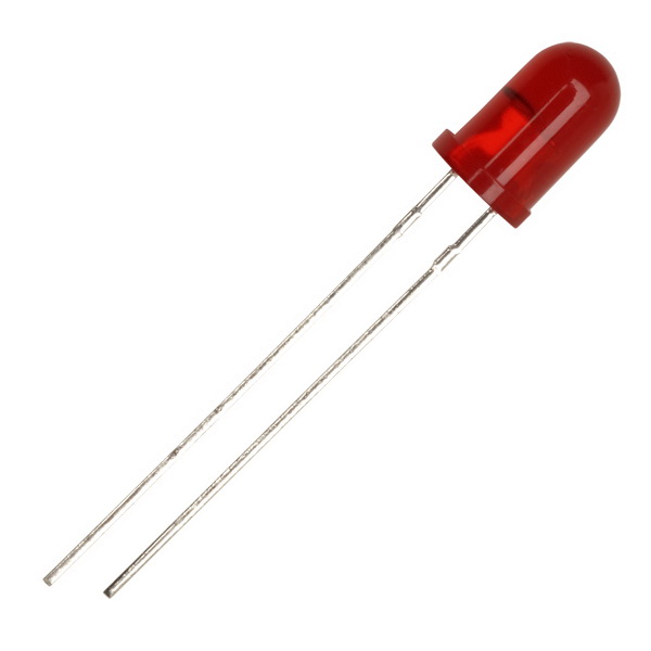
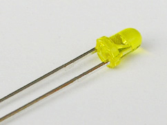
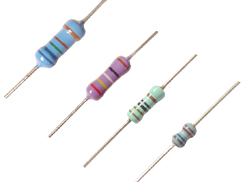
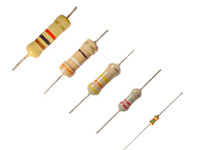
Next solder in the larger components. Be sure to orient the symmetrical components correctly. Make sure the positive and negative terminals of the LEDs and buzzer are in the correct holes, and that the transistor is facing the right way. The terminal blocks should have the screw clamps facing outward. On this diagram B1 is the buzzer, R9 is the 10K trimpot, T1 is the 2N3904 transistor, S1-S4 are the tactile switches, and J1-2 are the terminal blocks.