Logo Instruction Center
  • Login
  • Sign up
  • Forums
  • Store
  • Blog

Fun With Shift Registers

A tutorial to help you understand how a shift register works.
Steps
  1. Overview
  2. Getting to know the 74HC164
  3. The Schematic
  4. Breadboard Schematic
  5. Step 1: The Regulator
  6. Step 2: Placing The IC
  7. Step 3: Input Button
  8. Step 4: Clock Button
  9. Step 5: Bit #1
  10. Step 6: Repeat
  11. Step 7: Bit 5
  12. Step 8: More Bits

Add To Favorites
Categories
DIY Projects, Learning Projects
Created by takide
Status: Active
7393af6088c4f20303cc19ad007f616e?s=30

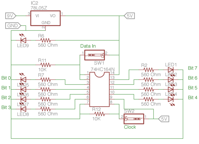
The Schematic Step 3 of 12

Here is the schematic for the circuit we will be building. This is for the more advanced builders. We will walk you through building the circuit in the next few steps.

Shift_register_tutorial

Next Page >>
<< Prev Page

Products

A-1554 LED 5mm Red Super Bright

R-carbon5_759 560 OHM 1/4W 5% Carbon Film Resistor

R-carbon5_809 10K OHM 1/4W 5% Carbon Film Resistor

Pdip-14_5 74HC164 74164 8-bit Serial Shift Register IC

Tc-0303-x_2 Tact Switch 6*6mm 5mm Through Hole SPST-NO

To-220-3-a_160 LM7805 L7805 7805 Voltage Regulator IC 5V 1.5A

A-2372 830 Point Solder-less Plug-in Breadboard

2025 © Tayda Electronics