Logo Instruction Center
  • Login
  • Sign up
  • Forums
  • Store
  • Blog

Fun With Shift Registers

A tutorial to help you understand how a shift register works.
Steps
  1. Overview
  2. Getting to know the 74HC164
  3. The Schematic
  4. Breadboard Schematic
  5. Step 1: The Regulator
  6. Step 2: Placing The IC
  7. Step 3: Input Button
  8. Step 4: Clock Button
  9. Step 5: Bit #1
  10. Step 6: Repeat
  11. Step 7: Bit 5
  12. Step 8: More Bits

Add To Favorites
Categories
DIY Projects, Learning Projects
Created by takide
Status: Active
7393af6088c4f20303cc19ad007f616e?s=30

Step 6: Repeat Step 10 of 12

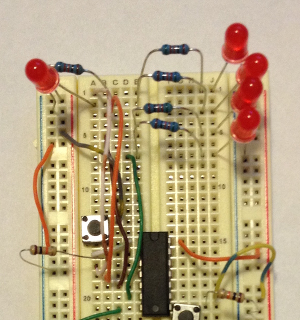
Now repeat what you did in step 5 for the rest of the outputs on the left side of the IC. You will have a row of 4 LED "bits" when you are finished:

Img_3466

Next Page >>
<< Prev Page

Products

A-1554 LED 5mm Red Super Bright

R-carbon5_759 560 OHM 1/4W 5% Carbon Film Resistor

R-carbon5_809 10K OHM 1/4W 5% Carbon Film Resistor

Pdip-14_5 74HC164 74164 8-bit Serial Shift Register IC

Tc-0303-x_2 Tact Switch 6*6mm 5mm Through Hole SPST-NO

To-220-3-a_160 LM7805 L7805 7805 Voltage Regulator IC 5V 1.5A

A-2372 830 Point Solder-less Plug-in Breadboard

2025 © Tayda Electronics