Protoboard for 1590B enclosure
This board simplifies building your DIY guitar pedal in a 1590B enclosure. Just build your effect circuit on the pre-perforated area of the PCB.Steps
Categories
Status: Active

PCB assembly Step 3 of 4
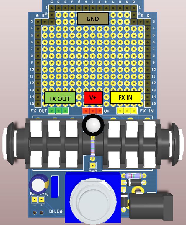
Each hole in the prototyping area is surrounded by a copper pad. There are also dedicated pads for the input (FX IN), output (FX OUT), voltage (V+), and ground (GND).
Your circuit can be built in a few simple steps:
-
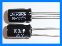
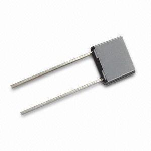
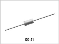
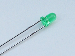
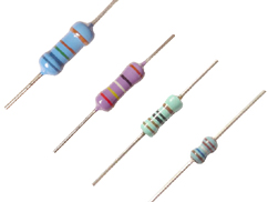
Place the Components: Place the resistors, diodes, capacitors, and transistors directly on the board. You can also place potentiometers or switches that will be mounted in the enclosure.
-
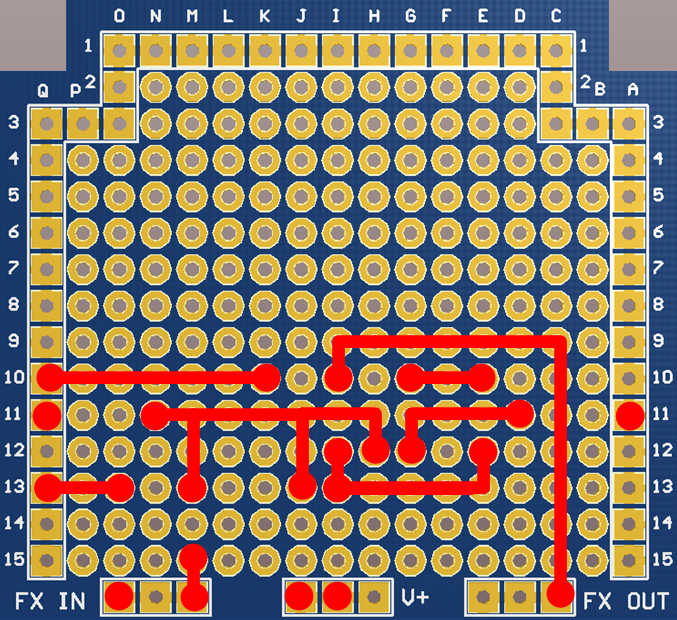
Plan the Wiring: Use both the top and bottom of the board for wiring. For a simpler circuit, start with the bottom side. For more complex circuits, use the top side as well and connect the pads between the two layers.
-
Connect the Components: Make your connections by wiring or by creating solder bridges from pad to pad. You can also use the legs of the components to bridge pads.
CIRCUIT EXAMPLE
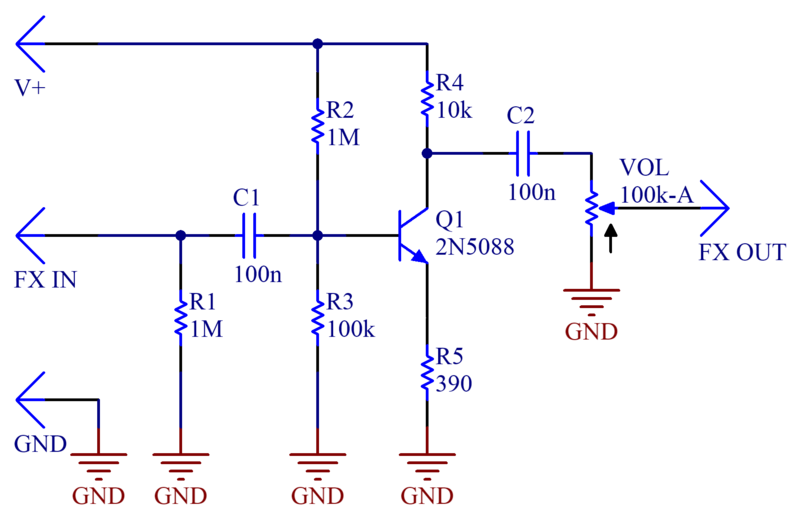
The figure below shows a BJT booster. The DH.E6 PCB already includes power supply filtering and reverse polarity protection.
Place all components on the top of the PCB. The potentiometer with angled legs can be mounted directly to the board as well. To ensure proper alignment, mount the potentiometer and the PCB in the enclosure first, then solder them into place.
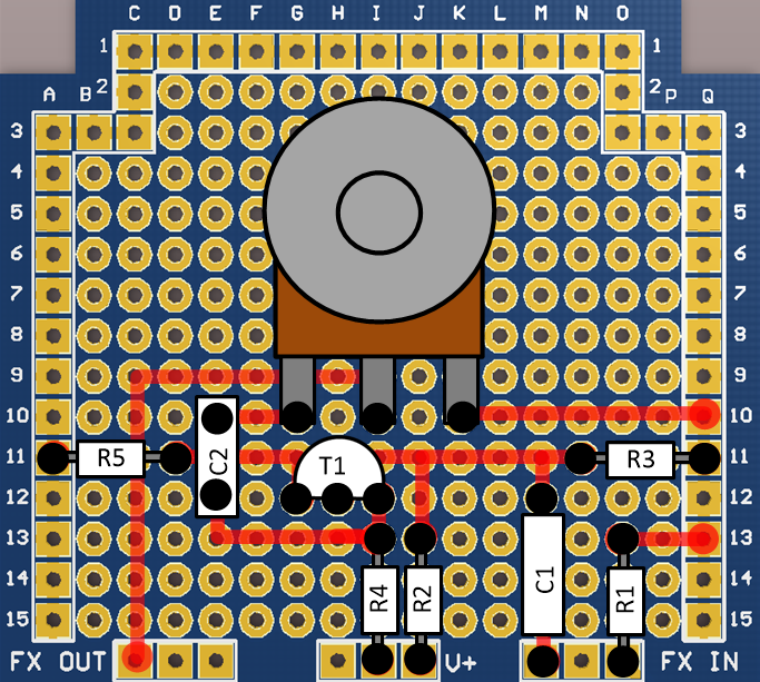
The components are connected by soldering the pads as indicated in the figure below. You can either use wires or create solder bridges directly between the pads.
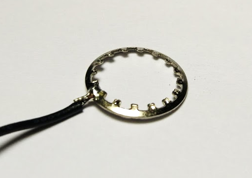
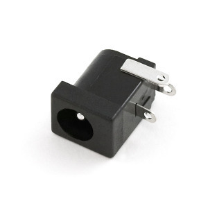
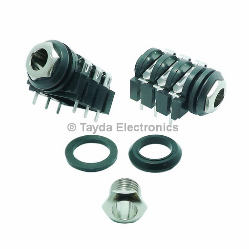
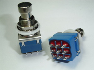
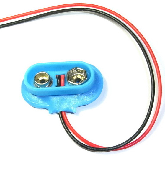
Before soldering the potentiometer, footswitch, jacks, and diode, first mount them in the enclosure to ensure proper alignment. Use the enclosure to position the components, adjusting the footswitch nut and washer height as needed. To align the DC jack, use an unpowered DC connector, ensuring it is centered in the hole and does not touch the enclosure. Finally, for the 9V battery clip, pass the wires through the two holes near the battery pads, then solder the red wire to the positive pad (+) and the black wire to the negative pad (-).
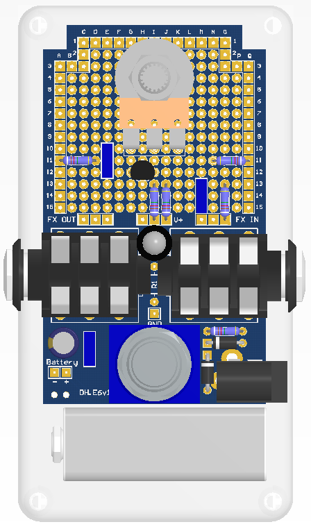
To minimize noise, ground the enclosure by soldering a wire between the "GND" pad on the PCB and the footswitch washer.