OpAmp Booster SMD
This op-amp booster PCB is based on the Micro Amp circuit and includes several tone settings. All components are pre-assembled, only the potentiometer and DIP switch need to be mounted to complete the build.Steps
Categories
Status: Active

PCB Step 2 of 4
COMPONENTS
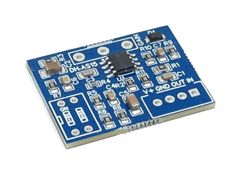
PCB
PCB OPAMP BOOSTER SMD PCB
Potentiometer
GAIN 500k-C 500KC ANTI-LOG TAPER POTENTIOMETER
DIP Switch
DIP SWITCH 2 POSITIONS (Optional)
Connector
4 PINS XH-2.54 MALE CONNECTOR (Optional)
PCB
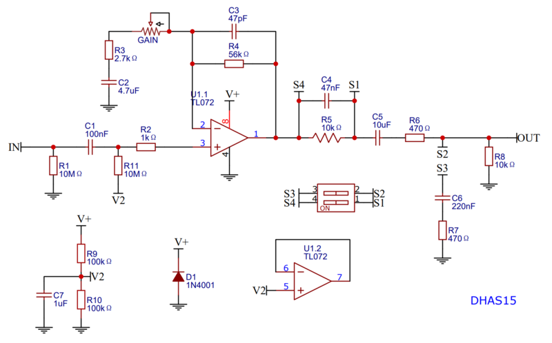
SCHEMATIC
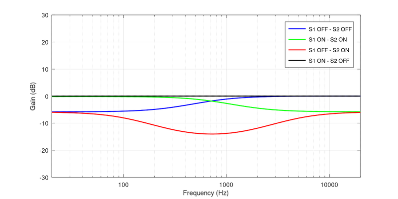
DIP SWITCH SETTINGS
Use a DIP switch for versatility, or wire jumpers to create a fixed configuration. With the switch in the "ON" position, the circuit is closed (shorted), which is the same as creating a permanent connection with a wire jumper.
 S1 ON, S2 OFF: Linear frequency response (original setting).
 S1 OFF, S2 OFF: High shelf filter with 6dB bass attenuation.
 S1 ON, S2 ON: Low shelf filter with 6dB treble attenuation.
 S1 OFF, S2 ON: Band filter with 6dB mids attenuation and 6dB overall gain attenuation.
The figure below shows the frequency response of the tone circuit for each configuration