Categories
Created by takide
Status: Active
Status: Active

Step 3: Building The Circuit Step 4 of 7
Now get out a piece of prototyping board. (Regular prototyping board is preffered, but stripboard will also work.)
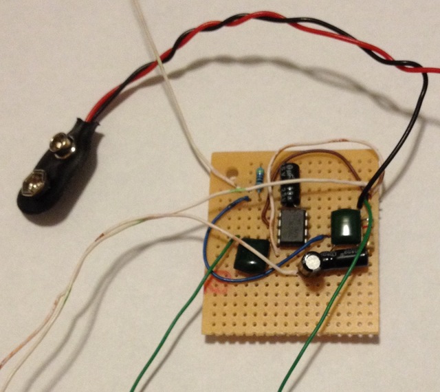
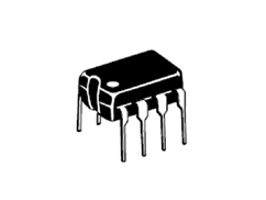
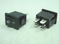
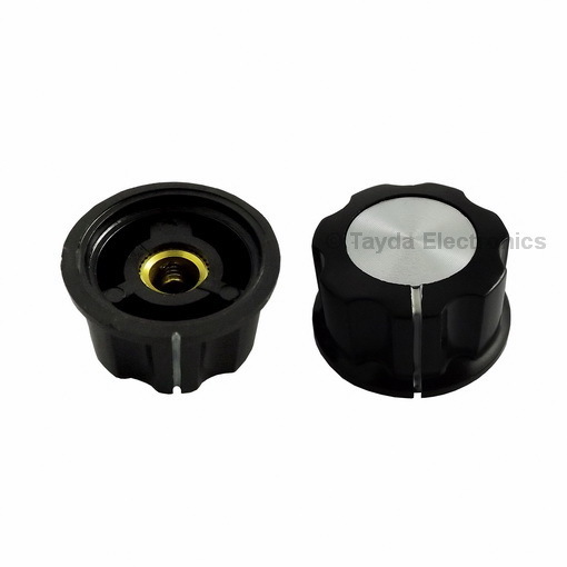
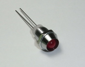
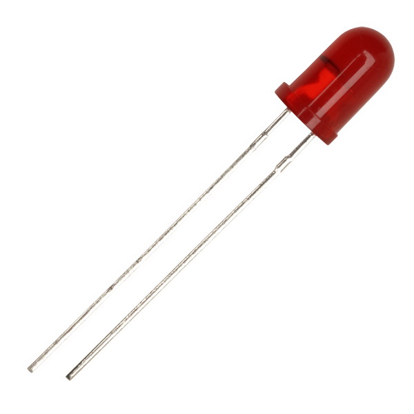
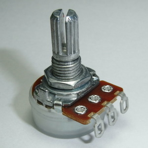
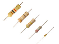
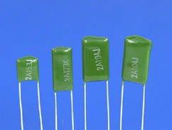
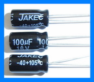
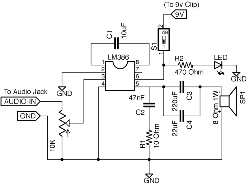
Place the LM386 IC near the middle of the board. Then arrange the other capacitors and resistors as shown in the schematic below. Remember to leave the speaker, audio jack, switch, LED, and potentiometer where they are mounted on the case.
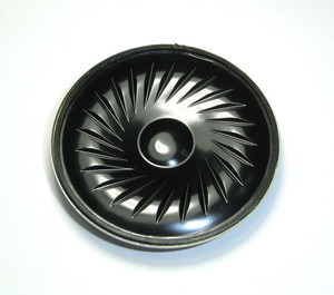
Next, be sure to solder wires that will go to the LED, switch, potentiometer, audio jack, and speaker. Keep track of where the wires go though!
Here is what the circuit board will look like after the wires are soldered to it: It can get messy, so double check where the wires go before soldering them in the next step!