Mini Guitar Amp (1590B)
This mini guitar amplifier is ideal for home practice, capable of driving speakers and headphones. It features tone and volume controls, with adjustable internal gain.Steps
Categories
Status: Active

PCB assembly Step 3 of 4
Use a soldering iron with a power rating of 15-30W and 0.5-1mm diameter solder wire. Safety Note: Soldering fumes are harmful to your eyes and lungs. Always work in a well-ventilated area.

To solder, first warm up the iron and clean the tip with a damp sponge. Apply heat simultaneously to both the PCB pad and the component's leg, then melt 1-3mm of solder onto the joint. Once cooled, trim the excess component leg. A proper solder joint should be shiny and fully cover the connection without touching adjacent pads. An improper or "cold" solder joint can result in a poor electrical connection.
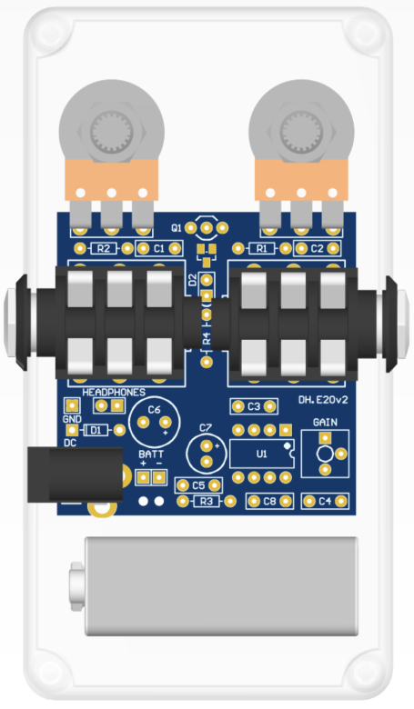
PCB ASSEMBLY
Solder the resistors, diodes, transitor, IC and capacitors onto their designated footprints on the board. For easier assembly, solder components in order of size, starting with the smallest and progressing to the largest.
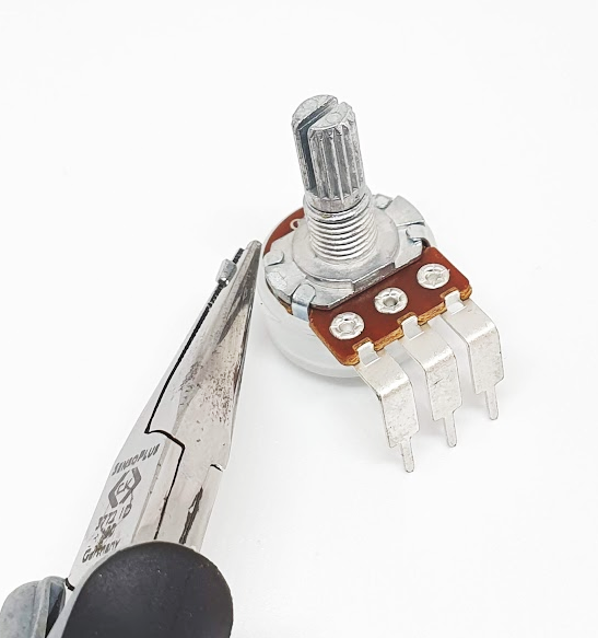
Use a pair of flat-nose pliers to snap off the anti-rotation tab on each potentiometer.
Mount the potentiometers, jacks, and LED into the enclosure before soldering to ensure proper alignment. To align the DC jack, use an unpowered DC connector, ensuring it is centered in the hole and does not touch the enclosure. Finally, for the 9V battery clip, pass the wires through the two holes near the battery pads, then solder the red wire to the positive pad (+) and the black wire to the negative pad (-).