Dual Looper
The Dual Loop allows you to alternate between two independent effects loops, providing two send/return paths controlled by a single footswitch.Steps
Categories
Status: Active

Enclosure and wiring Step 4 of 4
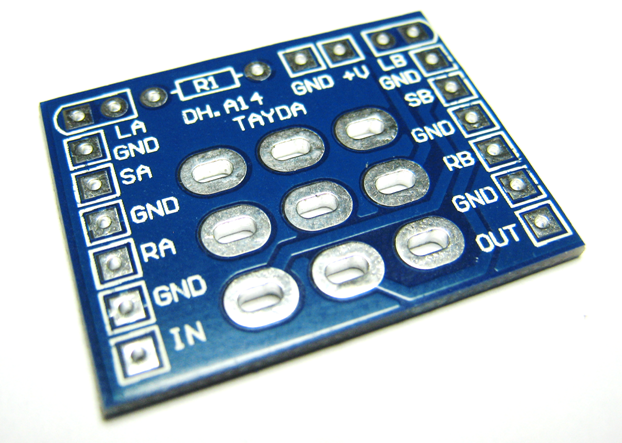
PLACEMENT
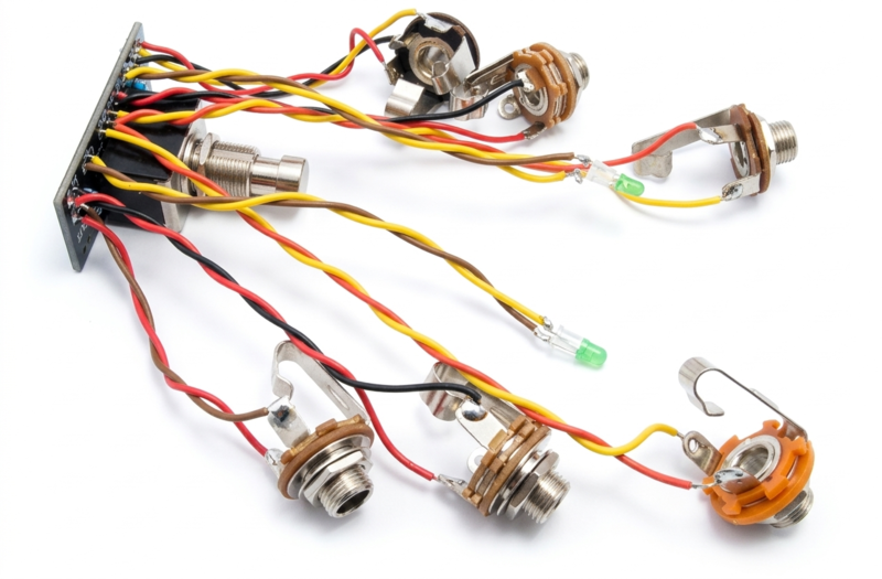
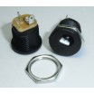
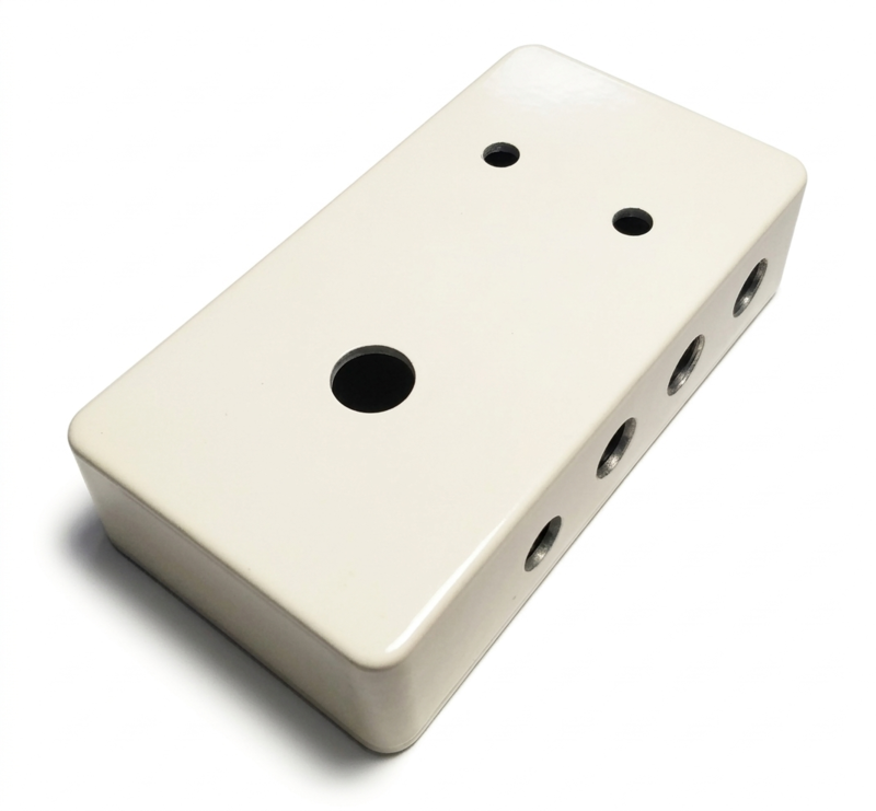
Place the assembled PCB and the rest of the components (DC and 3.5 jack connectors, 9V battery clip, 3PDT foot switch, led...) in a metal enclosure. Connect the ground of the circuit to the enclosure in order to attenuate the noise (the GND of the input and output jacks are in contact with the enclosure).
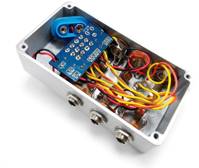
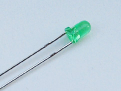
You can place the leds directly no the PCB or wire them. If you want to use the 1590B enclosure, you can place the DC jack directly on the PCB. You can also use other type of DC jack and wire it.
Place the assembled PCB and the remaining components (DC and 3.5mm jack connectors, 9V battery clip, 3PDT footswitch, LED, etc.) in a metal enclosure. Connect the ground of the circuit to the enclosure in order to attenuate the noise (the GND of the input and output jacks are in contact with the enclosure).
Mount the LEDs directly on the PCB or wire them. If using a 1590B enclosure, the DC jack can be mounted directly on the PCB. Alternatively, you can use a different type of DC jack and wire it separately.
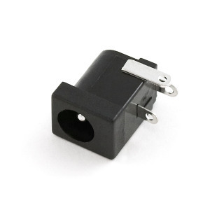
DC POWER JACK 2.1MM or DC POWER JACK 2.1MM PCB MOUNT
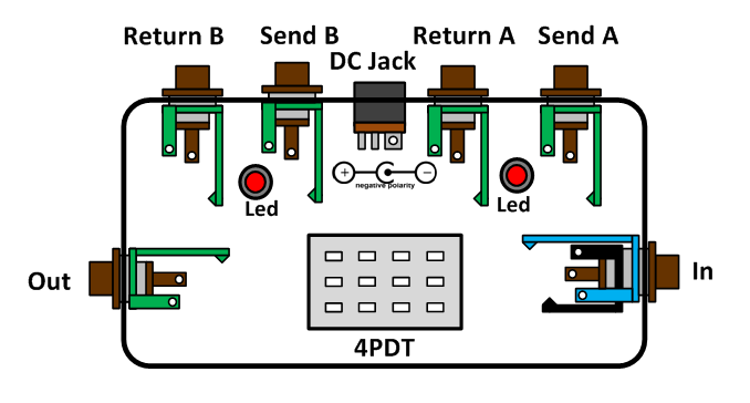
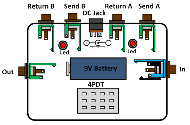
The following figures provide layout examples for 1590B and 1590BB enclosures.
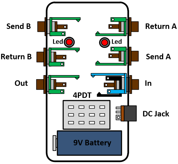

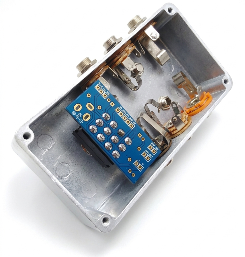
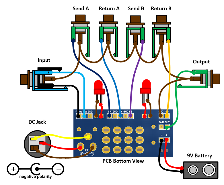
WIRING
For wiring, use a 24 AWG stranded wire and connect all components as shown in the following figure. The order in which you connect the grounds (GND) does not matter, as long as all elements are connected. The diagram below shows the wiring for a 2.1mm DC connector with a negative tip.