Fuzz Face
This is the Fuzz Face, the legendary fuzz pedal. With this PCB you can build the original or many other variants using either PNP or NPN transistors.Steps
Categories
Status: Active

Designators and components Step 2 of 5
COMPONENT LIST
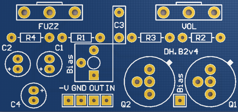
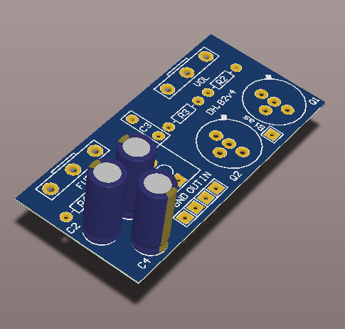
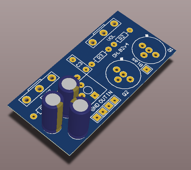
PCB
PCB FUZZ FACE DIY PCB GUITAR EFFECT
Capacitors
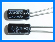
C1 2.2u 2.2UF 35V 105C RADIAL ELECTROLYTIC CAPACITOR 5X11MM
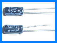
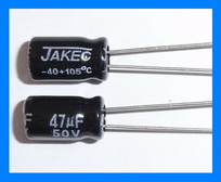
C2 22u 22UF 50V 105C RADIAL ELECTROLYTIC CAPACITOR 5X11MM
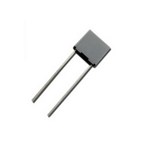
C3 10n 10NF 0.01UF 100V 5% POLYESTER FILM BOX TYPE CAPACITOR
C4 47u 47UF 25V 105C RADIAL ELECTROLYTIC CAPACITOR 5X11MM
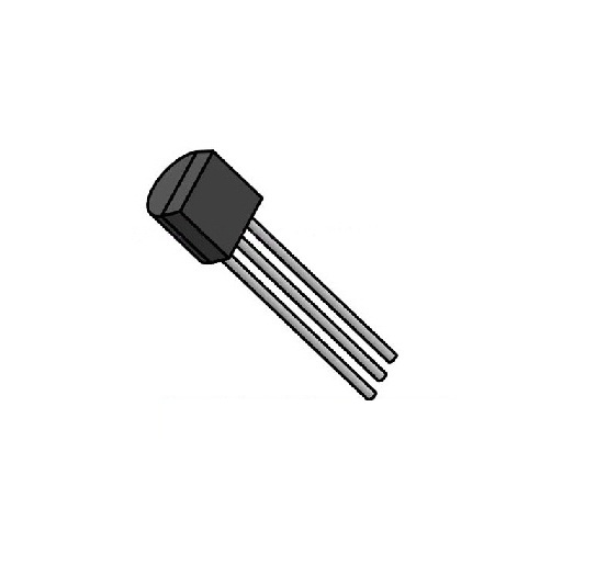
Transistors
Q1 PNP 2N3906 / NPN 2N3904, BC108 or BC109
Q2 PNP 2N3906 / NPN 2N3904, BC108 or BC109
Sockets 40 PIN DIP SIP IC SOCKETS ADAPTOR SOLDER TYPE
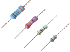
Resistors
R1 100k 100K OHM 1/4W 1% METAL FILM RESISTOR
R2 33k 33K OHM 1/4W 1% METAL FILM RESISTOR
R3 470 470 OHM 1/4W 1% METAL FILM RESISTOR
R4 1M 100K OHM 1/4W 1% METAL FILM RESISTOR (Optional)
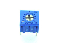
Bias 50k 50K OHM TRIMMER POTENTIOMETER
Potentiometers
FUZZ 1k-B 1K OHM LINEAR TAPER POTENTIOMETER
VOL 500k-A 500K OHM LOGARITHMIC TAPER POTENTIOMETER
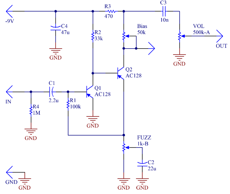
CIRCUIT
PCB
INPUT IMPEDANCE
For a classic Fuzz Face build, omit resistor R4. The resulting low input impedance interacts with passive pickups to attenuate high frequencies, smoothing the fuzz effect and making the circuit highly responsive to the guitar's volume knob.
The 1MΩ resistor at R4 acts as a pull-down resistor. Adding this resistor helps eliminate "switching pop" noise when engaging the effect and prevents high frequency attenuation.
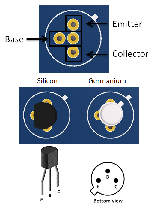
TRANSISTORS
The original Fuzz Face uses germanium PNP transistors (AC128 or NKT275). Use a low gain for Q1 (β=70-80) and a high gain for Q2 (β=110-130). Germanium transistors tend to have leakage current and a varying gain value. For the PNP silicon version, use 2N3906.
For NPN silicon version, use 2N3904, BC108 or BC109. To use to the negative ground version (NPN transistors), flip the polarity of the electrolytic capacitors (C1, C2, and C4) and connect the +9V power supply to the pad marked -9V.
Capacitors for PNP version Capacitors for NPN version
Refer to the images below for the correct transistor orientation.
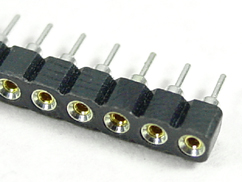
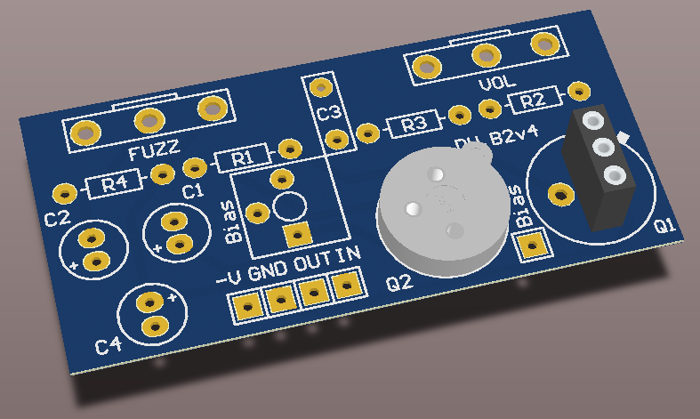
TRANSISTOR SOCKETS
For easy swapping and experimentation, use either 3-PIN HEADERS or dedicated transistor sockets.
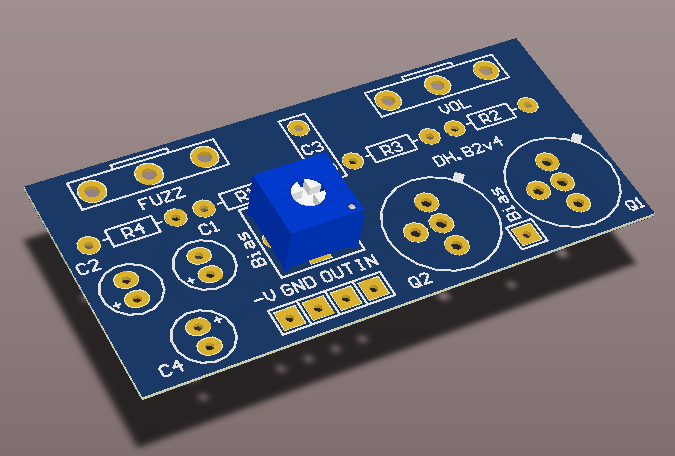
BIASING
Adjust the trimmer until the voltage at the "Bias" pad is 4.5V. Note that if you are using germanium transistors the biasing will be influenced by temperature.
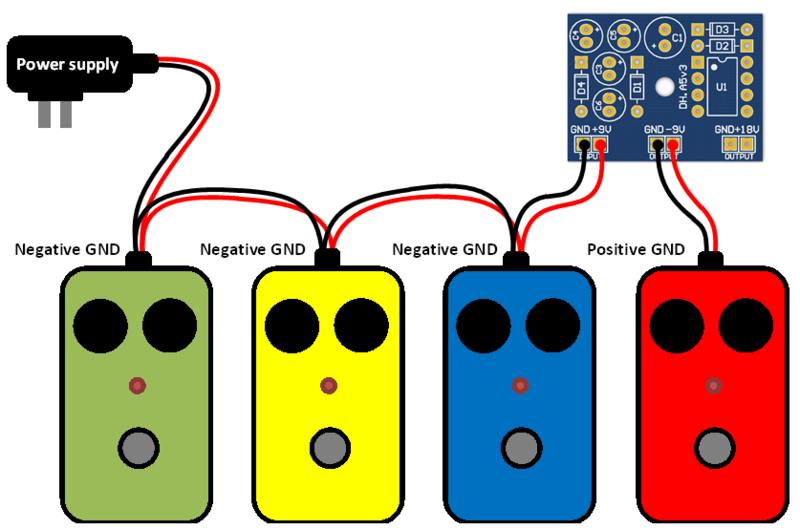
POWER SUPPLY CHAIN WITH POSITIVE GROUND PEDAL
A positive ground pedal cannot be directly connected to the power supply in chain with your other negative ground pedals. Use the Charge Pump PCB to build a voltage inverter and power your positive ground pedal in chain with the rest of your pedals.