Dual Loop Selector (1590B enclosure)
This is the Dual Loop for the 1590B enclosure. It lets you switch between two independent effects loops, providing two send/return paths controlled by a single footswitch.Steps
Categories
Status: Active

PCB assembly Step 3 of 4
Use a soldering iron with a power rating of 15-30W and 0.5-1mm diameter solder wire. Safety Note: Soldering fumes are harmful to your eyes and lungs. Always work in a well-ventilated area.

To solder, first warm up the iron and clean the tip with a damp sponge. Apply heat simultaneously to both the PCB pad and the component's leg, then melt 1-3mm of solder onto the joint. Once cooled, trim the excess component leg. A proper solder joint should be shiny and fully cover the connection without touching adjacent pads. An improper or "cold" solder joint can result in a poor electrical connection.
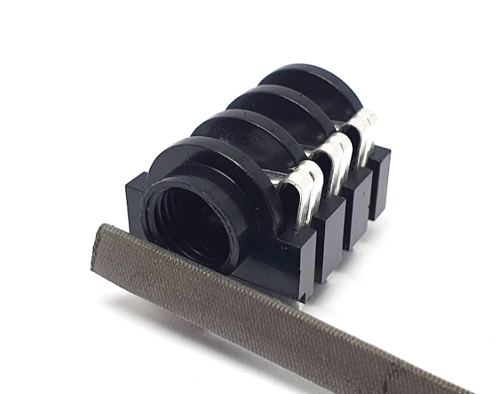
Use a flat metal file to remove a thin layer of plastic from the audio jacks. This will make mounting and removing the assembled PCB inside the enclosure much easier.
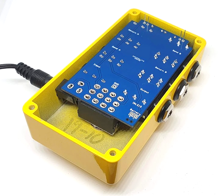
The assembly process is similar to the one for the DH.E14 PCB. Mount the footswitch, jacks, and diode in the enclosure. Adjust the height of the footswitch nut and washer. Use the enclosure itself to get the correct position for all components before you solder. To hold the DC jack, use an unpowered DC connector to keep it centered in the hole, ensuring it doesn't touch the enclosure.
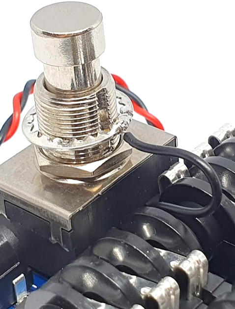
Connect the ground to the enclosure to reduce noise. Solder a cable between the pad marked "GND" on the PCB and the footswitch washer.
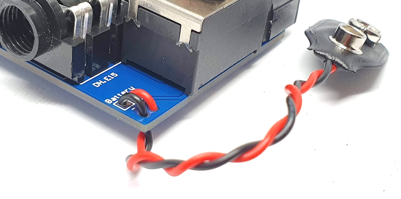
Pass the battery clip wires through the two holes near the battery pads. Solder the red wire to the positive pad (+) and the black wire to the negative pad (-).