Box of Metal
The Box of Metal is a high-gain distortion pedal designed for metal and hard rock. It incorporates a three-knob EQ for tone control.Steps
Categories
Status: Active

Designators and components Step 2 of 5
COMPONENT LIST
PCB
BOX OF METAL DIY PCB GUITAR EFFECT
Capacitors
C1 22n 22NF 0.022UF 100V 5% POLYESTER FILM BOX TYPE CAPACITOR
C2 10u 10UF 35V 105C JRB RADIAL ELECTROLYTIC CAPACITOR 5X11MM
C3 22n 22NF 0.022UF 100V 5% POLYESTER FILM BOX TYPE CAPACITOR
C4 1n 1NF 0.001UF 100V 5% POLYESTER FILM BOX TYPE CAPACITOR
C5 10n 10NF 0.01UF 100V 5% POLYESTER FILM BOX TYPE CAPACITOR
C6 22n 22NF 0.022UF 100V 5% POLYESTER FILM BOX TYPE CAPACITOR
C7 22n 22NF 0.022UF 100V 5% POLYESTER FILM BOX TYPE CAPACITOR
C8 100n 100NF 0.1UF 100V 5% POLYESTER FILM BOX TYPE CAPACITOR
C9 2.2n 2.2NF 0.0022UF 100V 5% POLYESTER FILM BOX TYPE CAPACITOR
C10 22n 22NF 0.022UF 100V 5% POLYESTER FILM BOX TYPE CAPACITOR
C11 22n 22NF 0.022UF 100V 5% POLYESTER FILM BOX TYPE CAPACITOR
C12 10u 10UF 35V 105C JRB RADIAL ELECTROLYTIC CAPACITOR 5X11MM
C13 100u 100UF 35V 105C RADIAL ELECTROLYTIC CAPACITOR 6X11MM
Diodes
D1 1N4739A 1N4739A 1N4739 ZENER DIODE 9.1V 1W
D1 1N4001 1N4001 DIODE 1A 50V
IC
Q1 BS170 BS170 BS170RLRAG MOSFET N-CHANNEL 60V 0.5A
Q2 BS170 BS170 BS170RLRAG MOSFET N-CHANNEL 60V 0.5A
Q3 BS170 BS170 BS170RLRAG MOSFET N-CHANNEL 60V 0.5A
Q4 BS170 BS170 BS170RLRAG MOSFET N-CHANNEL 60V 0.5A
Q5 BS170 BS170 BS170RLRAG MOSFET N-CHANNEL 60V 0.5A
Resistors
R1 1M 1M OHM 1/4W 1% METAL FILM RESISTOR ROYAL OHM TOP QUALITY
R2 2.2M 2.2M OHM 1/4W 1% METAL FILM RESISTOR ROYAL OHM TOP QUALITY
R3 2.2M 2.2M OHM 1/4W 1% METAL FILM RESISTOR ROYAL OHM TOP QUALITY
R4 1k 1K OHM 1/4W 1% METAL FILM RESISTOR ROYAL OHM TOP QUALITY
R5 5.1k 5.1K OHM 1/4W 1% METAL FILM RESISTOR ROYAL OHM TOP QUALITY
R6 2.2M 2.2M OHM 1/4W 1% METAL FILM RESISTOR ROYAL OHM TOP QUALITY
R7 1.2M 1.2M OHM 1/4W 1% METAL FILM RESISTOR ROYAL OHM TOP QUALITY
R8 2.2M 2.2M OHM 1/4W 1% METAL FILM RESISTOR ROYAL OHM TOP QUALITY
R9 2.2M 2.2M OHM 1/4W 1% METAL FILM RESISTOR ROYAL OHM TOP QUALITY
R10 5.1k 5.1K OHM 1/4W 1% METAL FILM RESISTOR ROYAL OHM TOP QUALITY
R11 470k 470K OHM 1/4W 1% METAL FILM RESISTOR ROYAL OHM TOP QUALITY
R12 2.2M 2.2M OHM 1/4W 1% METAL FILM RESISTOR ROYAL OHM TOP QUALITY
R13 2.2M 2.2M OHM 1/4W 1% METAL FILM RESISTOR ROYAL OHM TOP QUALITY
R14 5.1k 5.1K OHM 1/4W 1% METAL FILM RESISTOR ROYAL OHM TOP QUALITY
R15 220k 220K OHM 1/4W 1% METAL FILM RESISTOR ROYAL OHM TOP QUALITY
R16 2.2M 2.2M OHM 1/4W 1% METAL FILM RESISTOR ROYAL OHM TOP QUALITY
R17 2.2M 2.2M OHM 1/4W 1% METAL FILM RESISTOR ROYAL OHM TOP QUALITY
R18 5.1k 5.1K OHM 1/4W 1% METAL FILM RESISTOR ROYAL OHM TOP QUALITY
R19 Jumper (solder a cable over the footprint pads)
R20 2.2M 2.2M OHM 1/4W 1% METAL FILM RESISTOR ROYAL OHM TOP QUALITY
R21 2.2M 2.2M OHM 1/4W 1% METAL FILM RESISTOR ROYAL OHM TOP QUALITY
R22 5.1k 5.1K OHM 1/4W 1% METAL FILM RESISTOR ROYAL OHM TOP QUALITY
R23 47k 47K OHM 1/4W 1% METAL FILM RESISTOR ROYAL OHM TOP QUALITY
R24 100k 100K OHM 1/4W 1% METAL FILM RESISTOR ROYAL OHM TOP QUALITY
R25 100 100 OHM 1/4W 1% METAL FILM RESISTOR ROYAL OHM TOP QUALITY
BIAS 5k 5K OHM TRIMMER POTENTIOMETER CERMET 1 TURN 3362P
Potentiometers
GAIN 5k-C 5K OHM C5K 5KC ANTI-LOG TAPER POTENTIOMETER
VOLUME 100k-A 100K OHM LOGARITHMIC TAPER POTENTIOMETER
BASS 1M-A 1M OHM LOGARITHMIC TAPER POTENTIOMETER
MID 20k-A 20K OHM LOGARITHMIC TAPER POTENTIOMETER
TREB 250k-A 250K OHM LOGARITHMIC TAPER POTENTIOMETER
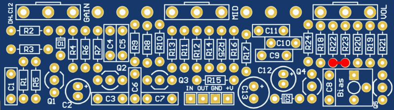
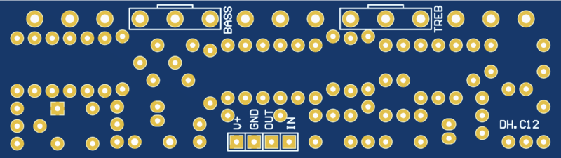
PCB
Note: there is a missing track on DHC12 PCB version, solder R22 and R23 pads as indicated in the following image.
SCHEMATIC
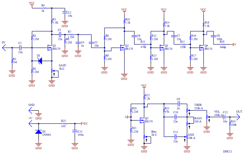
BIASING
Adjust Q5 gain with the varaible resistor "BIAS".
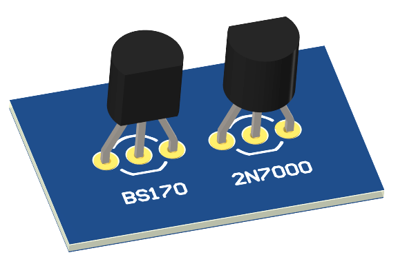
TRANSISTORS
The 2N7000 is a common replacement for BS170, however the pinout is a 180 degrees turn. Mount the transistors on the PCB as follows.