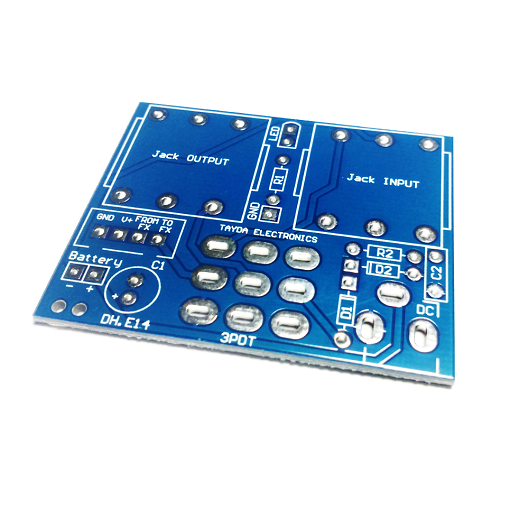
PCB for 1590B enclosure
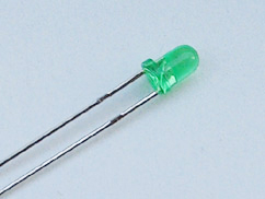
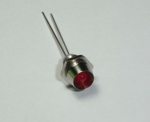
This PCB simplifies building your DIY guitar pedal in a 1590B enclosure. With the LED, jacks, and footswitch mounted directly to the board, you only need to wire the battery and the effect PCB.Steps
Categories
Status: Active

PCB assembly Step 4 of 5
Use a soldering iron with a power rating of 15-30W and 0.5-1mm diameter solder wire. Safety Note: Soldering fumes are harmful to your eyes and lungs. Always work in a well-ventilated area.

To solder, first warm up the iron and clean the tip with a damp sponge. Apply heat simultaneously to both the PCB pad and the component's leg, then melt 1-3mm of solder onto the joint. Once cooled, trim the excess component leg. A proper solder joint should be shiny and fully cover the connection without touching adjacent pads. An improper or "cold" solder joint can result in a poor electrical connection.
PCB ASSEMBLY
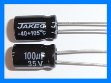
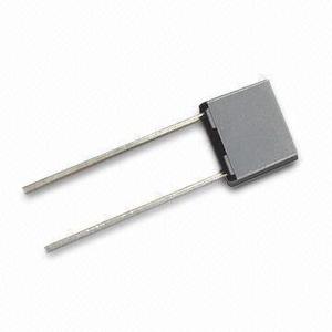
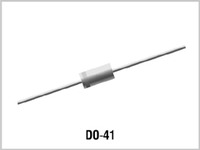
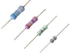
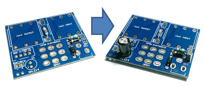
Solder the resistors, diodes, and capacitors onto their designated footprints on the board. For easier assembly, solder components in order of size, starting with the smallest and progressing to the largest.
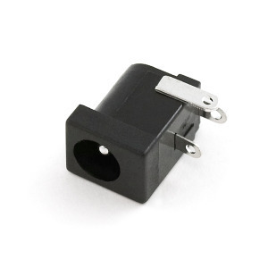
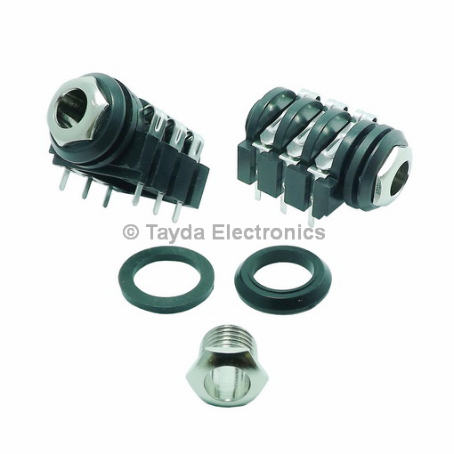
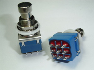
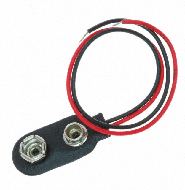
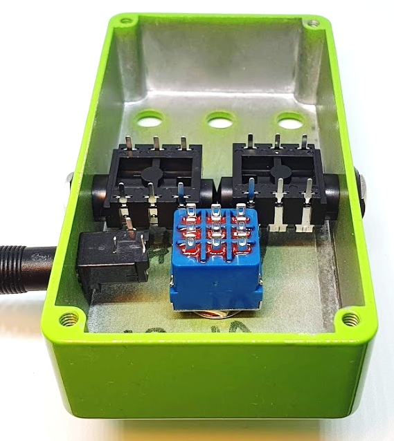
Before soldering the footswitch, jacks, and diode, first mount them in the enclosure to ensure proper alignment. Use the enclosure to position the components, adjusting the footswitch nut and washer height as needed. To align the DC jack, use an unpowered DC connector, ensuring it is centered in the hole and does not touch the enclosure. Finally, for the 9V battery clip, pass the wires through the two holes near the battery pads, then solder the red wire to the positive pad (+) and the black wire to the negative pad (-).
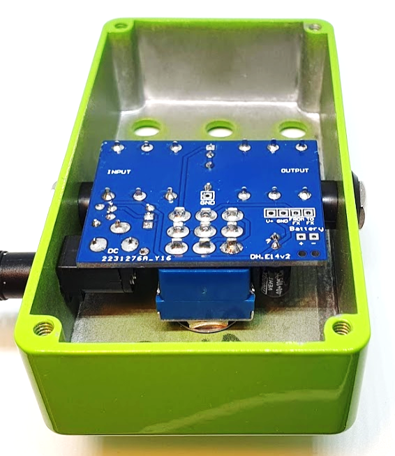
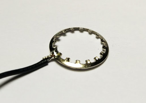
To minimize noise, ground the enclosure by soldering a wire between the "GND" pad on the PCB and the footswitch washer.