Created by DHEA
Status: Active
6ad5cfedb16d6a272994ad5c2b2b82c7?s=30

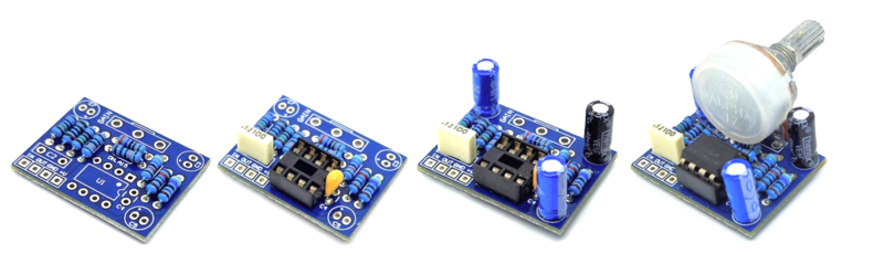
PCB assembly Step 3 of 5

Use a soldering pencil of 15-30W and solder wire of 1 mm diameter. The soldering will release fumes that are harmful to your eyes and lungs, work always in a well-ventilated area.

Warm up the soldering iron and clean the tip with a humid sponge. Heat the PCB pad and the component leg simultaneously and melt 1-3 mm of solder wire on the joint. Finally, cut the remaining of the component legs. Make sure the solder flows properly on both pad and component leg. If the solder has not been applied correctly, you could make a bad connection (cold solder joint). A good connection has to cover the joint without touching any adjacent pad.

Place the components on the footprints following the designators. You can place the components on both PCB sides, just keep the correct polarity. Solder the components from small to big size: resistors, diodes, capacitors, transistors, potentiometers...

GENERAL DESCRIPTION OF COMPONENTS

Resistors

The resistors should be ¼ Watt metal type. You can either use a multimeter or the color bands to obtain their values. Resistors do not have polarity, you can place them in any direction.

Electrolytic capacitors

Electrolytic capacitors have their value printed on them. The negative polarity pin is indicated by a white strip along the can. They also have a longer leg indicating the positive pin. The maximum voltage rating never can be exceeded, make sure you are using at least double voltage rating than your power supply. For example, if you are using a 9V power supply, use a electrolytic capacitor with at least 18V maximum voltage rating.

Polyester capacitors

The polyester capacitors have their value marked with three numbers. Read as picofarads (pF), the first two are the 1st and 2nd digits and the third is the multiplier code. These capacitors do not have polarity, you can place them in any direction.

Ceramic capacitors

The ceramic capacitors have their value marked with three numbers. Read as picofarads (pF), the first two are the 1st and 2nd digits and the third is the multiplier code. These capacitors do not have polarity, you can assemble them in any direction.

Tantalum capacitors

Tantalum capacitors have the value printed on them. The polarity is marked for the positive pin. Additionally, the longer leg is the positive and shorter the negative. Assemble the tantalum capacitor according to the positive polarity (+) marked on the PCB.

Integrated Circuits

Integrated Circuits (ICs) have their model printed on them. A notch half-circle or a dot indicates the correct position of the IC on the PCB.

Diodes

Diodes have their model printed on them. The polarity (cathode) is indicated by the ring near the side. This ring is also marked on the PCB.

Led diodes

Led diodes have polarity, the cathode is indicated as a flat surface on the side of the diode and also it is the shorter led. On the PCB, the cathode is marked as a flat side and anode as a round side.

Transistors

Transistors are three terminals components and their model is printed on them. To indicate the correct orientation, one side of the transistor is flat and the other one is round.

Potentiometers

Potentiometers have their resistance value marked on them. They are marked with A, B or C for logarithmic, linear and reverse logarithmic, respectively.

Trimpots

Trimpots are similar to potentiometers. Their values are printed on them. Use a small screwdriver to adjust them.