Orange Squeezer
The Orange Squeezer is a classic and simple DIY guitar project. This circuit provides smooth and effective compression, perfect for controlling and shaping your guitar's dynamics.Steps
Categories
Status: Active

Designators and components Step 2 of 5
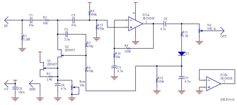
COMPONENT LIST
PCB
PCB ORANGE SQUEEZER PCB
Resistors
R1 2.2M 2.2M OHM 1/4W 1% METAL FILM RESISTOR
R2 82k 82K OHM 1/4W 1% METAL FILM RESISTOR
R3 470k 470K OHM 1/4W 1% METAL FILM RESISTOR
R4 390k 390K OHM 1/4W 1% METAL FILM RESISTOR
R5 2.4k 2.4K OHM 1/4W 1% METAL FILM RESISTOR
R6 470k 470K OHM 1/4W 1% METAL FILM RESISTOR
R9 220k 220K OHM 1/4W 1% METAL FILM RESISTOR
R10 10k 10K OHM 1/4W 1% METAL FILM RESISTOR
R11 1.5k 1.5K OHM 1/4W 1% METAL FILM RESISTOR
R12 100k 100K OHM 1/4W 1% METAL FILM RESISTOR
R13 470k 470K OHM 1/4W 1% METAL FILM RESISTOR
Capacitors
C1 47n 47NF 100V 5% POLYESTER FILM BOX TYPE CAPACITOR
C2 2.2n 2.2NF 0.0022UF 100V 5% POLYESTER FILM BOX TYPE CAPACITOR
C3 47n 47NF 100V 5% POLYESTER FILM BOX TYPE CAPACITOR
C4 4.7u 4.7UF 35V 105C RADIAL ELECTROLYTIC CAPACITOR 5X11MM
C5 4.7u 4.7UF 35V 105C RADIAL ELECTROLYTIC CAPACITOR 5X11MM
C6 4.7u 4.7UF 35V 105C RADIAL ELECTROLYTIC CAPACITOR 5X11MM
C7 4.7u 4.7UF 35V 105C RADIAL ELECTROLYTIC CAPACITOR 5X11MM
C8 100u 100UF 35V 105C RADIAL ELECTROLYTIC CAPACITOR 6X11MM
Diodes
D1 1N34 1N34A GERMANIUM DIODE
IC
IC1 4558 NJM4558 4558 DUAL OPERATIONAL AMPLIFIER GENERAL PURPOSE IC
Transistors
Q1 2N5457 2N5457 JFET N-CHANNEL TRANSISTOR SMD
Q2 2N5457 2N5457 JFET N-CHANNEL TRANSISTOR SMD
Potentiometers
VOL 10k-A 10K OHM LOGARITHMIC TAPER POTENTIOMETER
BIAS 10k 10K OHM TRIMMER POTENTIOMETER CERMET
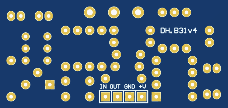
PCB SCHEMATIC
PCB
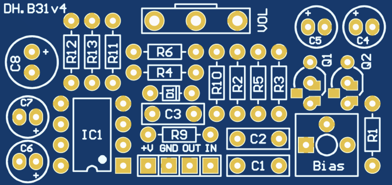
The PCB is compatible with both through-hole and SMD n-type JFET transistors (e.g., J201, 2N5457, 2N5458, MPF102). Be sure to align the pinout with the figure below.
![]()
BIASING
Use the trimpot to enable the compression effect. As you adjust the trimmer, the compression will intensify, but it will also introduce distortion. Adjust the trimpot until you hear the sound begin to distort, then dial it back to find the ideal balance between compression and clarity. This sweet spot is often found around the middle of the trimmer’s range.