Linear Power Booster
This is the iconic LPB booster, delivering a gain boost with added clarity and definition. Use it to drive your amplifier into smooth saturation for a richer and more dynamic sound.Steps
Categories
Status: Active

Enclosure and wiring Step 4 of 5
PLACEMENT
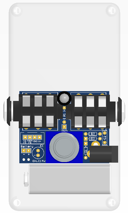
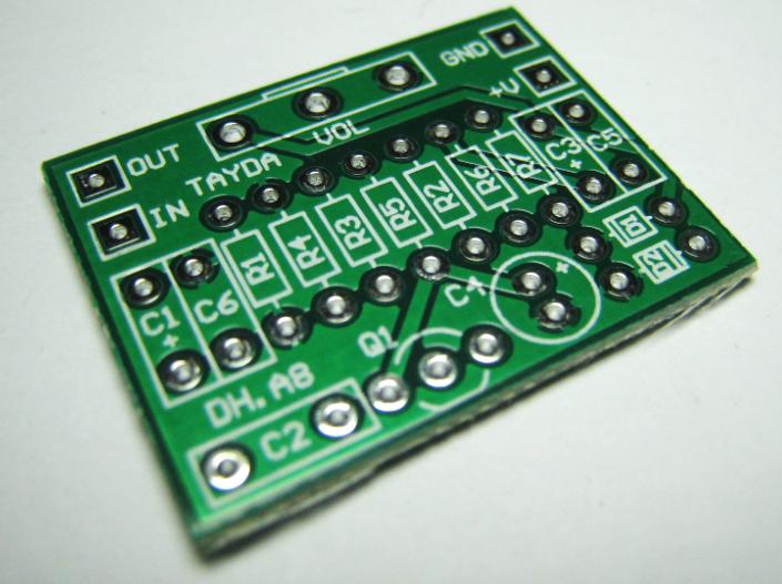
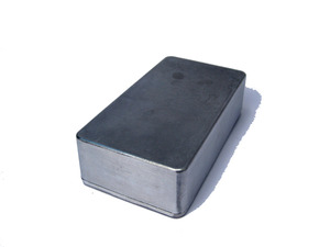
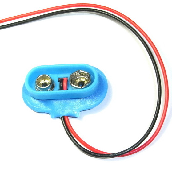
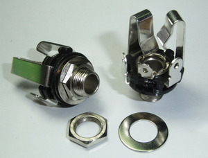
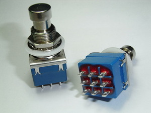
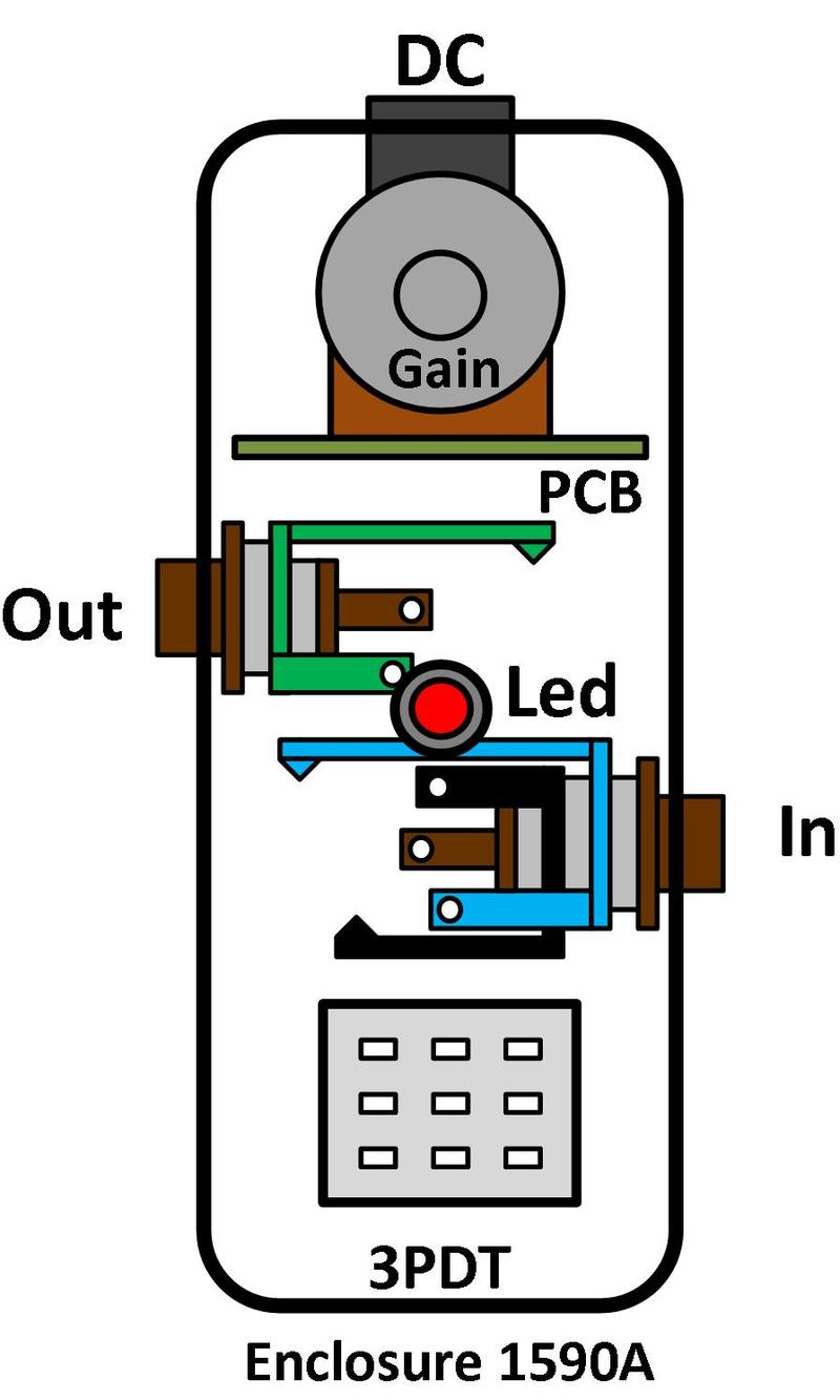
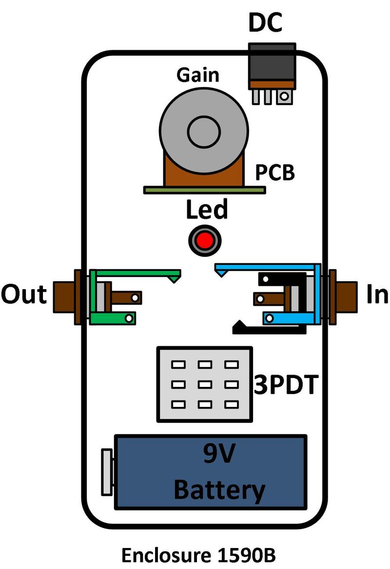
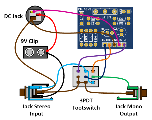
Mount the assembled PCB and the rest of the components (DC jack, input/output jacks, 9V battery clip, 3PDT foot switch, led...) in a metal enclosure. Connect the ground of the circuit to the enclosure (the ground of the jacks are in contact with the enclosure). The following figures show the components mounted in both 1590A and 1590B enclosures.
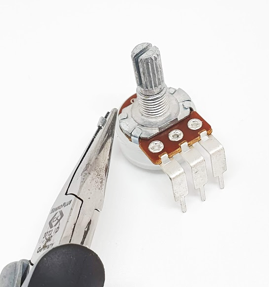
Use a pair of flat-nose pliers to snap off the anti-rotation tab on each potentiometer.
WIRING
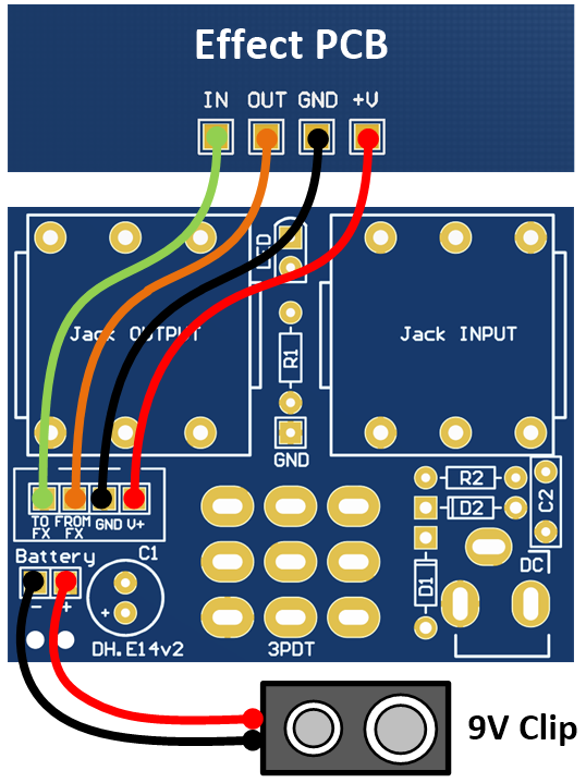
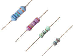
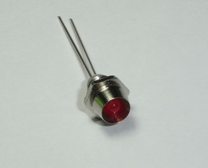
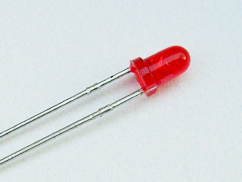
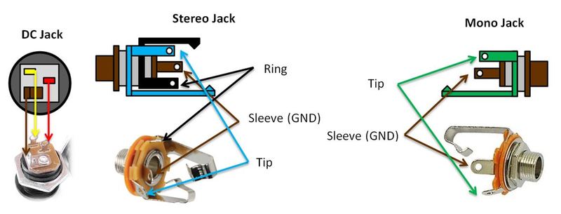
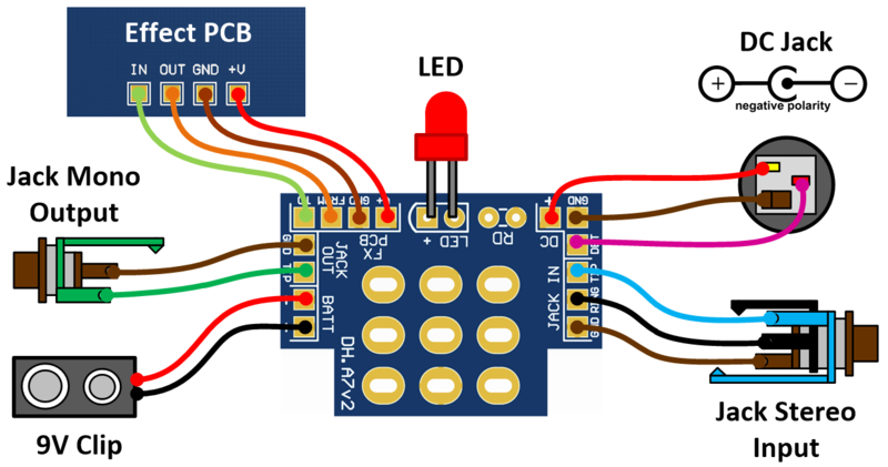
Use a 24 AWG stranded wire to connect all components as shown in the following figure. The order in which you connect the ground (GND) does not matter, as long as all components are eventually connected. The diode led requires a current limiter resistor, a value between 2.2kΩ and 4.7kΩ is recommended for standard LEDs. The figure below shows the wiring for a negative-tip DC connector.
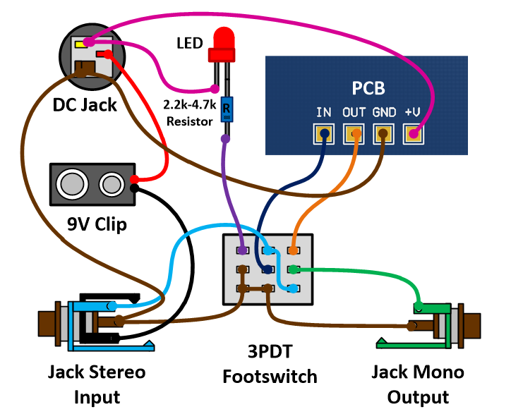
Wiring for the Led mounted on the effect PCB
PCB FOR 3PDT FOOTSWITCH (PCB and Instructions)
This PCB simplifies wiring and helps you create a neat circuit with reduced noise. It also includes dedicated pads for the LED and its current-limiting resistor.
PCB FOR 1590B ENCLOSURE (PCB and Instructions)
This PCB simplifies building your DIY guitar pedal in a 1590B enclosure. With the LED, jacks, and footswitch mounted directly to the board, you only need to wire the battery and the effect PCB.
To connect the 1590B PCB and the effect PCB, you can either mount a XH 4-pin male connector or solder wires directly as shown in the following figure. The PCB pins are labeled as "GND", "+V", "FROM FX", and "TO FX". Connect the "FROM FX" pin to the output of the effect PCB and the "TO FX" pin to the input of the effect PCB.