Timmy Overdrive
The Timmy Overdrive provides a classic transparent overdrive with a huge versatility thanks to the three clipping options.Steps
Categories
Status: Active

PCB assembly Step 3 of 5
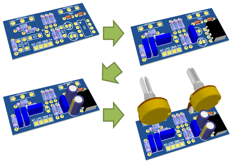
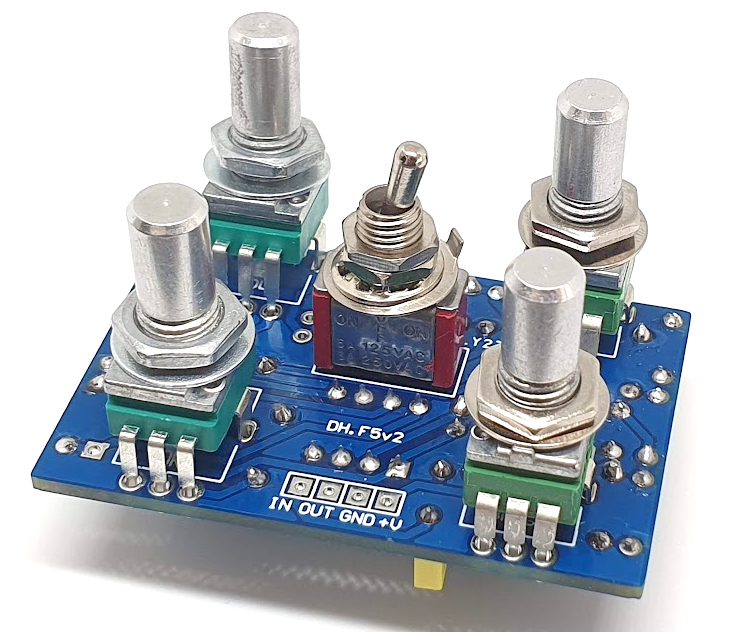
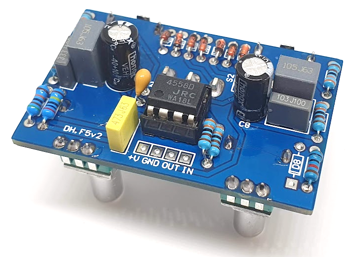
The PCB is designed to mount the 9 mm vertical potentiometers and the switch directly on it. Follow the footprints for the correct positioning, as indicated in the following figures.
Use a soldering pencil of 15-30W and solder wire of 1 mm diameter. The soldering will release fumes that are harmful to your eyes and lungs, work always in a well-ventilated area.

Warm up the soldering iron and clean the tip with a humid sponge. Heat the PCB pad and the component leg simultaneously and melt 1-3 mm of solder wire on the joint. Finally, cut the remaining of the component legs. Make sure the solder flows properly on both pad and component leg. If the solder has not been applied correctly, you could make a bad connection (cold solder joint). A good connection has to cover the joint without touching any adjacent pad.
Place the components on the footprints following the designators. You can place the components on both PCB sides, just keep the correct polarity. Solder the components from small to big size: resistors, diodes, capacitors, transistors, potentiometers...