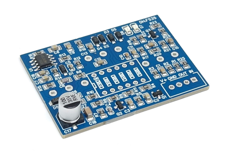
SD-1 Distortion SMD
This assembled PCB is based on the classic DS-1 circuit and features six switches for customizing gain, clipping, and tone.Steps
Categories
Status: Active

PCB Step 2 of 4
COMPONENTS
Potentiometers
GAIN 1M-A 1M OHM Log POTENTIOMETER
VOL 100K-B 100K OHM LINEAR POTENTIOMETER
TONE 20K-W 20K OHM W-TAPER POTENTIOMETER + DUST SEAL
DIP Switch
DIP SWITCH 6 POSITIONS (Optional)
Connector
4 PINS XH-2.54 MALE CONNECTOR (Optional)
PCB
SCHEMATIC
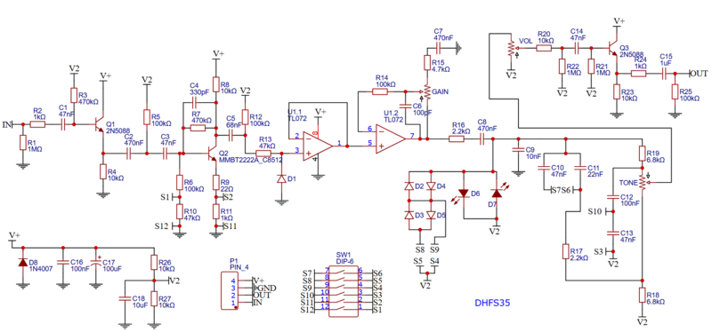
DIP SWITCH SETTINGS
S1 and S2: Gain 
S1 OFF, S2 OFF: original gain setting.
S1 ON, S2 ON: lower gain.
S4 and S5: Clipping diodes 
S4 OFF, S5 OFF: one pair of LED diodes. Most transparent and least compressed sound.
S4 ON, S5 OFF: one pair of silicon diodes. Original setting. More compressed sound.
S4 OFF, S5 ON: two pairs silicon diodes. More transparent and less compressed sound.
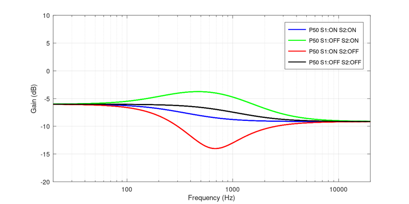
S3 and S6: Tone control 
S3 OFF, S6 OFF: Pot at 50%: flatter tone. Pot at max: more bass. Pot at min: more treble.
S3 ON, S6 OFF: original tone setting. Mids scoop.
S3 OFF, S6 ON: mids hump.
S3 ON, S6 ON: Pot at 50%: flatter tone. Pot at max: less bass. Pot at min: less treble.
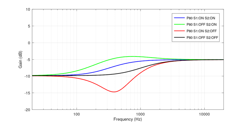
The following are the frequency responses of the tone section for the potentiometer at 20%, 50% and 80%.
Tone 20%
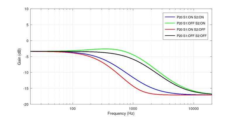
Tone 50%
Tone 80%