RAT Distortion SMD
This assembled PCB is based on the RAT circuit with footprints for four DIP switches to customize clipping and bass.Steps
Categories
Status: Active

PCB Step 2 of 4
COMPONENTS
Potentiometers
TONE 100k-A 100K OHM LOG POTENTIOMETER + DUST SEAL
VOL 100k-A 100K OHM LOG POTENTIOMETER + DUST SEAL
GAIN 100k-A 100K OHM LOG POTENTIOMETER + DUST SEAL
DIP Switch
DIP SWITCH 4 POSITIONS (Optional)
Connector
4 PINS XH-2.54 MALE CONNECTOR (Optional)
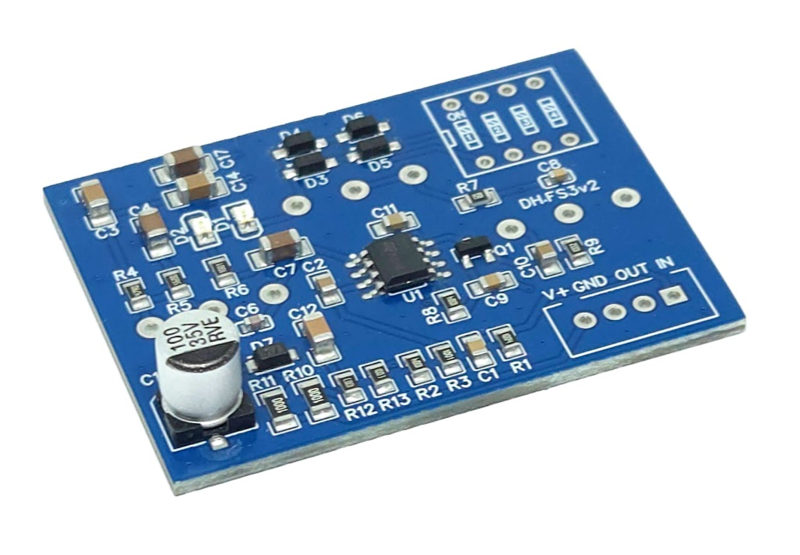
PCB
SCHEMATIC
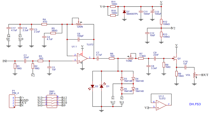
DIP SWITCH SETTINGS
S1 and S2: Clipping diodes 
S1 OFF, S2 OFF: one pair of LED diodes. Most transparent and least compressed sound.
S1 ON, S2 ON: one pair of silicon diodes. Original setting. More compressed sound.
S1 OFF, S2 ON: two pairs silicon diodes. More transparent and less compressed sound.
S3 and S4: Bass control (fat mod) 
S3 OFF, S4 OFF: original bass setting.
S3 ON, S4 OFF: extra bass 1.
S3 OFF, S4 ON: extra bass 2.
S3 ON, S4 ON: extra bass 3.