Range Master (with DC inverter)
This is the legendary Rangemaster booster equipped with a DC inverter for PNP transistors and a treble frequency selector.Steps
Categories
Status: Active

Designators and components Step 2 of 5
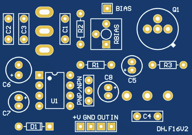
PCB DESIGNATORS (FOR POSITIVE GROUND PNP VERSION)
PCB
PCB RANGE MASTER WITH DC INVERTER PCB
Capacitors
C1 4.7n 4.7NF 0.0047UF 100V POLYESTER FILM BOX TYPE CAPACITOR
C2 22n 22NF 100V 5% POLYESTER FILM BOX TYPE CAPACITOR
C3 100n 100NF 100V POLYESTER FILM BOX TYPE CAPACITOR
C4 10n 10NF 100V 5% POLYESTER FILM BOX TYPE CAPACITOR
C5 47u 47UF 25V 105C RADIAL ELECTROLYTIC CAPACITOR 5X11MM
C6 100u 100UF 35V 105C RADIAL ELECTROLYTIC CAPACITOR 6X11MM
C7 10u 10UF 50V 105C ALUMINUM ELECTROLYTIC CAPACITOR 5X11MM
C8 10u 10UF 50V 105C ALUMINUM ELECTROLYTIC CAPACITOR 5X11MM
Switch
SW SPDT ON/OFF/ON MINI TOGGLE SWITCH ON-OFF-ON
Transistors
Q1 PNP 2N3906 / NPN 2N3904, BC108 or BC109
Socket 40 PIN DIP IC SOCKETS ADAPTOR
OPAMP
U1 TC1044SCPA TC1044SCPA TC1044 VOLTAGE REGULATOR IC
(Socket 8 PIN DIP IC SOCKET ADAPTOR)
Resistors
R1 1M 1M OHM 1/4W METAL FILM RESISTOR
R2 470k 470K OHM 1/4W METAL FILM RESISTOR
R3 3.9k 3.9K OHM 1/4W METAL FILM RESISTOR
Bias 100k 100K OHM TRIMMER POTENTIOMETER 1 TURN
Potentiometer
Boost 10k-A 10K OHM LOGARITHMIC POTENTIOMETER + DUST SEAL
PCB
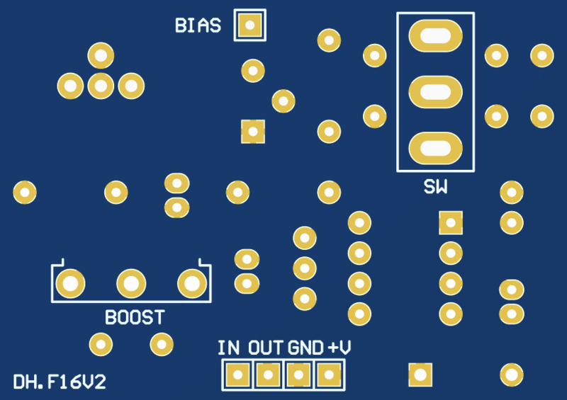
PCB SCHEMATIC
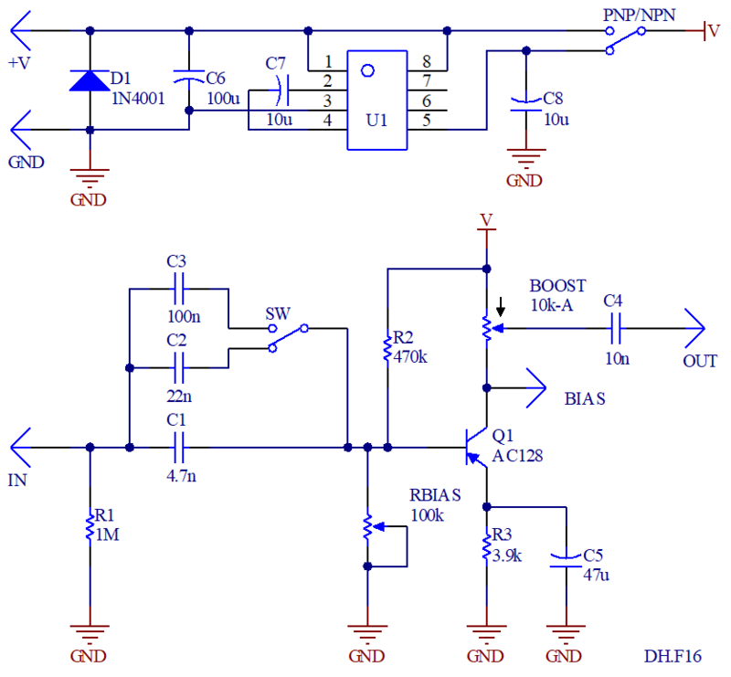
PNP/NPN VERSION
The PCB is designed to build both positive and negative grounds. To create the positive-ground (PNP transistor) version, simply place a jumper over the PNP/NPN pads as shown below.

For the NPN version, do not mount components C7, C8, and U1. Make the jumper over the PNP/NPN pads as shown below.

BIASING
Use the trimpot to bias the circuit. Use a voltmeter to measure the voltage on the "Bias" pad and adjust to -7 V (+7 V if using NPN). Note that if you are using germanium transistors the biasing will be influenced by temperature.
TRANSISTORS
The original Rangemaster uses a germanium PNP transistor with gain between 75 and 100 (OC44). For the PNP silicon version, use 2N3906. For the NPN silicon version, use 2N3904, BC108 or BC109.
Use 3 pin headers (40 PIN DIP SIP IC SOCKETS ADAPTOR or a transistor socket.
TREBLE SELECTOR
Select the input and output capacitors (C1, C2, C3, and C4) to adjust the amount of low frequency amplification. A higher capacitance value will result in more low frequency amplification. Experiment with values between 2.2nF and 100nF.
The toggle switch lets you select between three treble configurations:
-
Center Position: Uses capacitor C1 (e.g., 4.7nF)
-
Up Position: Combines C1 and C2 (e.g., 4.7nF + 22nF = 26.7nF)
-
Down Position: Combines C1 and C3 (e.g., 4.7nF + 100nF = 104.7nF)
If not frequency selector is required, dont mount the toggle switch, C2 and C3.