JFET preamp
This JFET preamplifier delivers a fantastic tube-like sound. The circuit is exceptionally simple to build and can be used as a versatile booster.Steps
Categories
Status: Active

Designators and components Step 2 of 5
COMPONENT LIST
This PCB can be used to build a several projects. The following components are for the FETZER preamplifier.
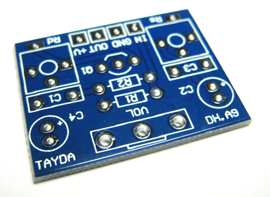
PCB JFET PREAMP DIY PCB
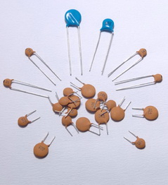
C1 220p 220PF 50V CERAMIC DISC CAPACITOR
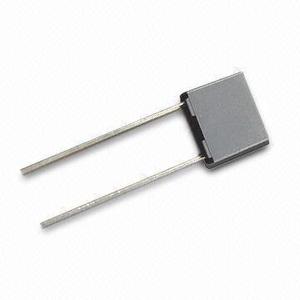
C3 47n 47NF 100V 5% POLYESTER FILM BOX TYPE CAPACITOR
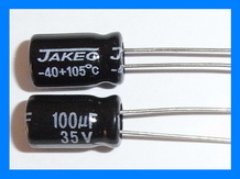
C4 100u 100UF 35V ELECTROLYTIC CAPACITOR 6X11MM
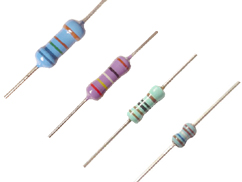
R1 1M 1M OHM 1/4W 1% METAL FILM RESISTOR
R2 33k 33K OHM 1/4W 1% METAL FILM RESISTOR
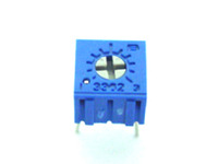
Rd 50k 50K TRIMMER POTENTIOMETER
Rs 10k 10K TRIMMER POTENTIOMETER
Q1 J201 MMBFJ201 SOT-23 JFET N-CHANNEL TRANSISTOR J201 SMD
VOL 100k-A 100K OHM AUDIO POTENTIOMETER
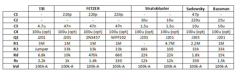
The value "-" in the table means that the component is not mounted. Experiment with other component values and design your own custom JFET preamp. For more information on FET guitar preamplifiers, here are a couple of great resources to get you started.
http://www.till.com/articles/GuitarPreamp/
http://www.runoffgroove.com/fetzervalve.html
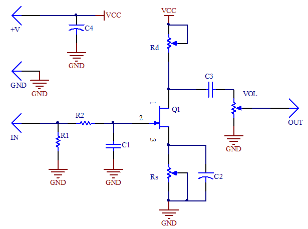
SCHEMATIC
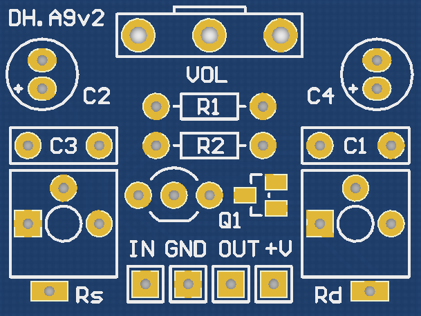
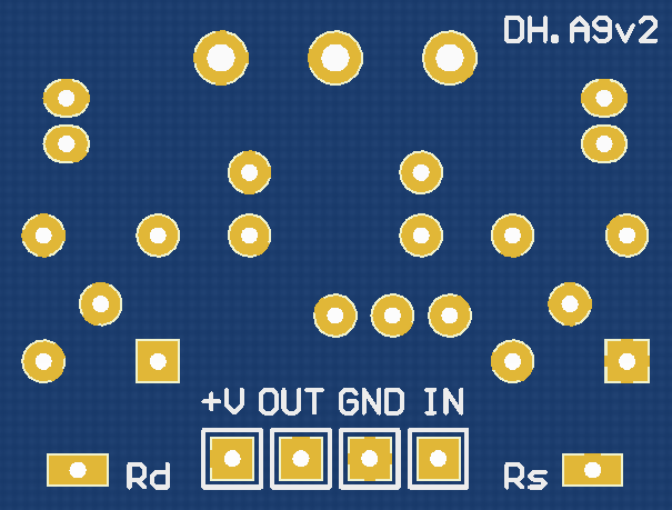
PCB
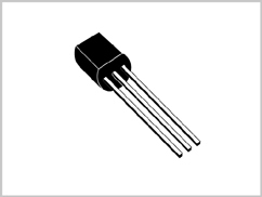
TRANSISTOR
This PCB is compatible with both through-hole and SMD n-type JFET transistors (e.g., J201, 2N5457, 2N5458, MPF102). Be sure to align the pinout with the figure below.
![]()
BIASING
Use trimpots that are at least twice the expected value of Rs and Rd. To set the desired bias point, measure and adjust the votlages at the designated "Rs" and "Rd" pads.
For a maximum dynamic range and a cleaner sound, set the bias to half of the power supply voltage. For a warmer and more saturated sound, increase the biasing voltage at "Rd".