Fuzz Factory 1590B
The Fuzz Factory is an iconic five-knob fuzz pedal with a huge range of sound possibilities. This project is designed to fit into a compact 1590B enclosure.Steps
Categories
Status: Active

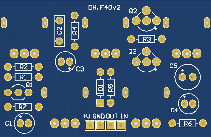
Designators and components Step 2 of 5
COMPONENT LIST
PCB
PCB FUZZ FACTORY 1590B DIY PCB GUITAR EFFECT
Capacitors
C1 10u 10UF 25V 105C RADIAL ELECTROLYTIC CAPACITOR 5X11MM
C2 100n 100NF 0.1UF 100V 5% POLYESTER FILM BOX TYPE CAPACITOR
C3 10u 10UF 25V 105C RADIAL ELECTROLYTIC CAPACITOR 5X11MM
C4 10u 10UF 25V 105C RADIAL ELECTROLYTIC CAPACITOR 5X11MM
C5 47u 47UF 50V 105C RADIAL ELECTROLYTIC CAPACITOR 6X11MM
Diodes
D1 1N4001 1N4001 DIODE 1A 50V
Transistors
Q1 2N3904 2N3904 NPN GENERAL PURPOSE TRANSISTOR
Q2 2N3906 2N3906 PNP GENERAL PURPOSE TRANSISTOR
Q3 2N3906 2N3906 PNP GENERAL PURPOSE TRANSISTOR
Q2/Q3 Socket 40 PIN 2.54MM DIP SIP IC SOCKETS ADAPTOR SOLDER TYPE
Resistors
R1 220k 220K OHM 1/4W 1% METAL FILM RESISTOR
R2 10k 10K OHM 1/4W 1% METAL FILM RESISTOR
R3 470 470 OHM 1/4W 1% METAL FILM RESISTOR
R4 47k 47K OHM 1/4W 1% METAL FILM RESISTOR
R5 5.1k 5.1K OHM 1/4W 1% METAL FILM RESISTOR
R6 220k 220K OHM 1/4W 1% METAL FILM RESISTOR
R7 1M 1M OHM 1/4W 1% METAL FILM RESISTOR (Optional)
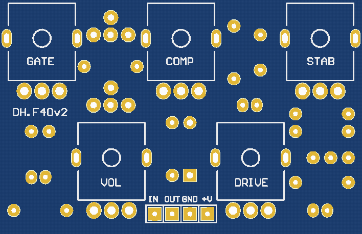
Potentiometers
STAB 5k-B 5K OHM LINEAR TAPER POTENTIOMETER
VOL 5k-B 5K OHM LINEAR TAPER POTENTIOMETER
COMP 10k-B 10K OHM LINEAR TAPER POTENTIOMETER
DRIVE 10k-B 10K OHM LINEAR TAPER POTENTIOMETER
GATE 10k-B 10K OHM LINEAR TAPER POTENTIOMETER
PCB
SCHEMATIC
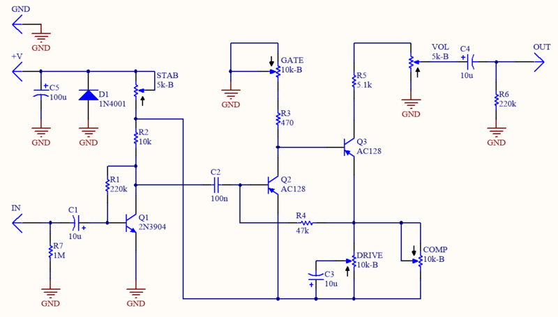
INPUT IMPEDANCE
For a classic Fuzz Factory build, omit resistor R7. The resulting low input impedance interacts with passive pickups to attenuate high frequencies, smoothing the fuzz effect and making the circuit highly responsive to the guitar's volume knob.
The 1MΩ resistor at R7 acts as a pull-down resistor. Adding this resistor helps eliminate "switching pop" noise when engaging the effect and prevents high frequency attenuation.
TRANSISTORS
You can use either germanium (Q2 AC128, Hfe 60-80 and Q3 AC128, Hfe 100-120) or silicon (2N3906) transistors. Refer to the figures below for the correct orientation of the transistors.
![]()
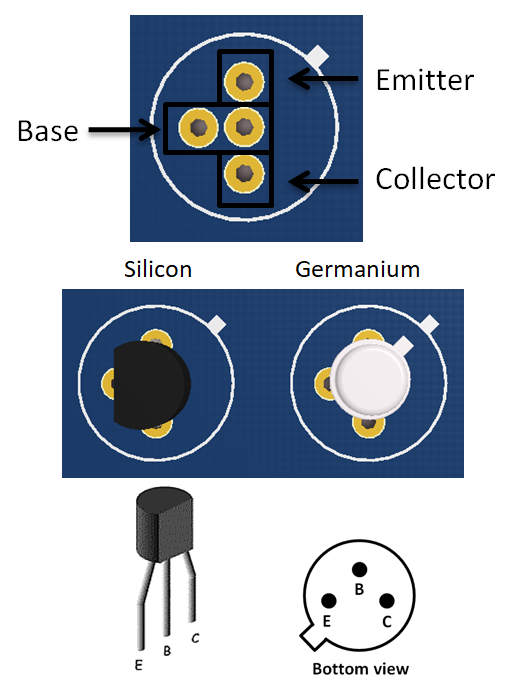
TRANSISTOR SOCKETS
For easy swapping and experimentation, use either 3-PIN HEADERS or dedicated transistor sockets.
![]()