Full Drive
The Full Drive is a very popular and versatile overdrive pedal featuring multiple clipping options and a boost stage.Steps
Categories
Status: Active

Designators and components Step 2 of 5
COMPONENT LIST
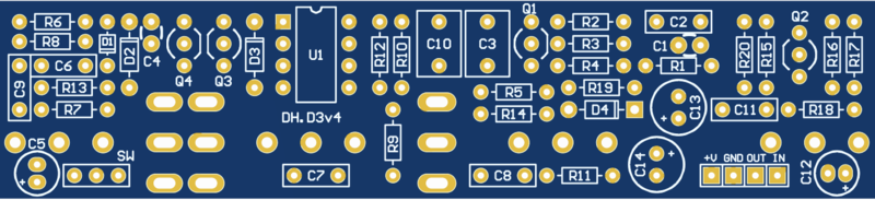
PCB
PCB FULL DRIVE DIY PCB GUITAR EFFECT
Resistors
R1 1M 1M OHM 1/4W 1% METAL FILM RESISTOR
R2 1k 1K OHM 1/4W 1% METAL FILM RESISTOR
R3 510k 510K OHM 1/4W 1% METAL FILM RESISTOR
R4 10k 10K OHM 1/4W 1% METAL FILM RESISTOR
R5 10k 10K OHM 1/4W 1% METAL FILM RESISTOR
R6 4.7k 4.7K OHM 1/4W 1% METAL FILM RESISTOR
R7 22k 22K OHM 1/4W 1% METAL FILM RESISTOR
R8 22k 22K OHM 1/4W 1% METAL FILM RESISTOR
R9 1k 1K OHM 1/4W 1% METAL FILM RESISTOR
R10 10k 10K OHM 1/4W 1% METAL FILM RESISTOR
R11 220 220 OHM 1/4W 1% METAL FILM RESISTOR
R12 1k 1K OHM 1/4W 1% METAL FILM RESISTOR
R13 47k 47K OHM 1/4W 1% METAL FILM RESISTOR
R14 1k 1K OHM 1/4W 1% METAL FILM RESISTOR
R15 510k 510K OHM 1/4W 1% METAL FILM RESISTOR
R16 10k 10K OHM 1/4W 1% METAL FILM RESISTOR
R17 100 100 OHM 1/4W 1% METAL FILM RESISTOR
R18 82k 82K OHM 1/4W 1% METAL FILM RESISTOR
R19 10k 10K OHM 1/4W 1% METAL FILM RESISTOR
R20 10k 10K OHM 1/4W 1% METAL FILM RESISTOR
Capacitors
C1 10p 10PF 50V CERAMIC DISC CAPACITOR
C2 22n 22NF 100V 5% POLYESTER FILM BOX TYPE CAPACITOR
C3 1u 1UF 100V 5% POLYESTER FILM BOX TYPE CAPACITOR
C4 50p 50PF 50V CERAMIC DISC CAPACITOR
C5 10u 10UF 50V ELECTROLYTIC CAPACITOR 5X11MM
C6 100n 100NF 100V 5% POLYESTER FILM BOX TYPE CAPACITOR
C7 220n 220NF 100V 5% POLYESTER FILM BOX TYPE CAPACITOR
C8 220n 220NF 100V 5% POLYESTER FILM BOX TYPE CAPACITOR
C9 10n 10NF 100V 5% POLYESTER FILM BOX TYPE CAPACITOR
C10 1u 1UF 100V 5% POLYESTER FILM BOX TYPE CAPACITOR
C11 100n 100NF 100V 5% POLYESTER FILM BOX TYPE CAPACITOR
C12 10u 10UF 50V ELECTROLYTIC CAPACITOR 5X11MM
C13 100u 100UF 35V ELECTROLYTIC CAPACITOR 6X11MM
C14 100u 100UF 35V ELECTROLYTIC CAPACITOR 6X11MM
Diodes
D1 1N914 1N914 SMALL SIGNAL DIODE 200MA 100V
D2 1N4001 1N4001 DIODE 1A 50V
D3 1N34 1N34 GERMANIUM DIODE
D4 1N4001 1N4001 DIODE 1A 50V
IC
U1 JRC4558 4558 DUAL OPERATIONAL AMPLIFIER
Transistors
Q1 2N5088 2N5088 GERENAL PURPOSE TRANSISTOR
Q2 2N5088 2N5088 GERENAL PURPOSE TRANSISTOR
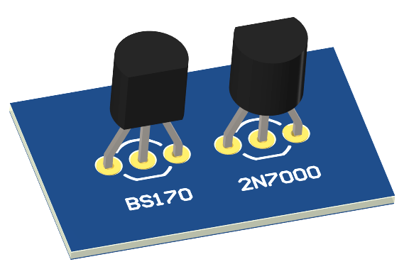
Q3 BS170 BS170 BS170RLRAG MOSFET N-CHANNEL
Q4 BS170 BS170 BS170RLRAG MOSFET N-CHANNEL
Switches
SW MINI TOGLE SWITCH ON-ON
FCVB MINI TOGLE SWITCH ON-ON-ON
Potentiometers
VOL 100k-A 100K OHM LOG POTENTIOMETER
TONE 25k-B 25K OHM LINEAR POTENTIOMETER
DRIVE 500k-A 500K OHM LOG POTENTIOMETER
BOOST 1M-B 1m OHM LINEAR POTENTIOMETER
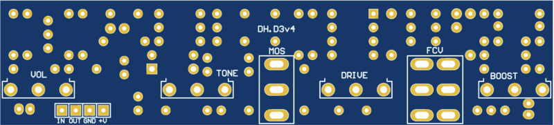
PCB
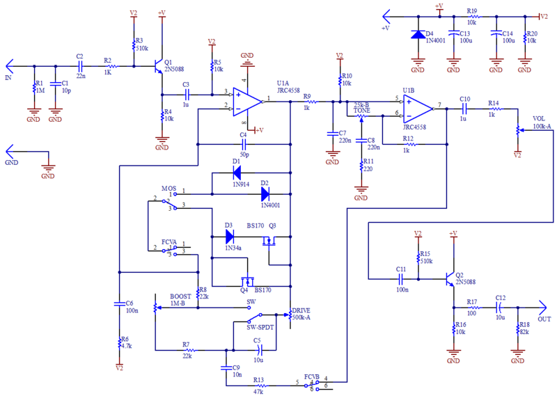
SCHEMATIC
TRANSISTORS
The 2N7000 is a common replacement for the BS170, however the pinout is a 180 degrees turn. Mount the transistors on the PCB as follows.