Eternity
This guitar pedal delivers a very smooth overdrive similar to the saturation generated by a vacuum tube. It is ideal for blues and rock, providing excellent sustain.Steps
Categories
Status: Active

Designators and components Step 2 of 5
PCB DESIGNATORS
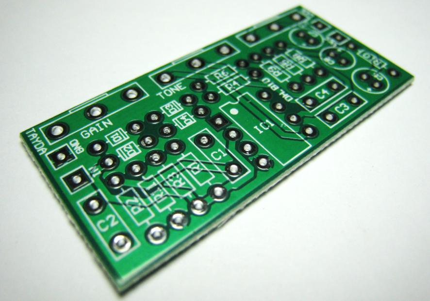
PCB
PCB ETERNITY DIY PCB
Capacitors
C1 100n 100NF 100V 5% POLYESTER FILM BOX TYPE CAPACITOR
C2 47n 47NF 100V 5% POLYESTER FILM BOX TYPE CAPACITOR
C3 150n 150NF 100V 5% POLYESTER FILM BOX TYPE CAPACITOR
C4 220n 220NF 100V 5% POLYESTER FILM BOX TYPE CAPACITOR
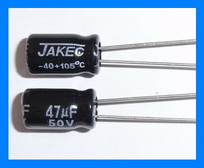
C5 10u 10UF 50V ELECTROLYTIC CAPACITOR 5X11MM
C7 47u 47UF 25V ELECTROLYTIC CAPACITOR 5X11MM
C8 47u 47UF 25V ELECTROLYTIC CAPACITOR 5X11MM
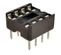
IC
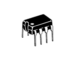
IC1 NJM4558 NJM4558D IC DUAL OPERATIONAL AMPLIFIER
IC Socket 8PIN IC DIP SOCKET
Diodes
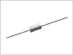
D1 1N914 1N914 SMALL SIGNAL DIODE 200MA 100V
D2 1N914 1N914 SMALL SIGNAL DIODE 200MA 100V
D3 1N914 1N914 SMALL SIGNAL DIODE 200MA 100V
D4 1N914 1N914 SMALL SIGNAL DIODE 200MA 100V (Optional)
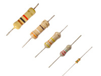
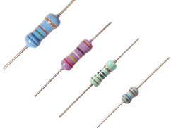
Resistors
R1 3.3k 3.3K OHM 1/4W 1% METAL FILM RESISTOR
R2 1M 1M OHM 1/4W 1% METAL FILM RESISTOR
R3 20k 20K OHM 1/4W 1% METAL FILM RESISTOR
R4 1k 1K OHM 1/4W 1% METAL FILM RESISTOR
R5 330 330 OHM 1/4W 1% METAL FILM RESISTOR
R6 1k 1K OHM 1/4W 1% METAL FILM RESISTOR
R8 330 330 OHM 1/4W 1% METAL FILM RESISTOR
R9 10k 10K OHM 1/4W 1% METAL FILM RESISTOR
R10 10k 10K OHM 1/4W 1% METAL FILM RESISTOR
R11 1M 1M OHM 1/4W 1% METAL FILM RESISTOR
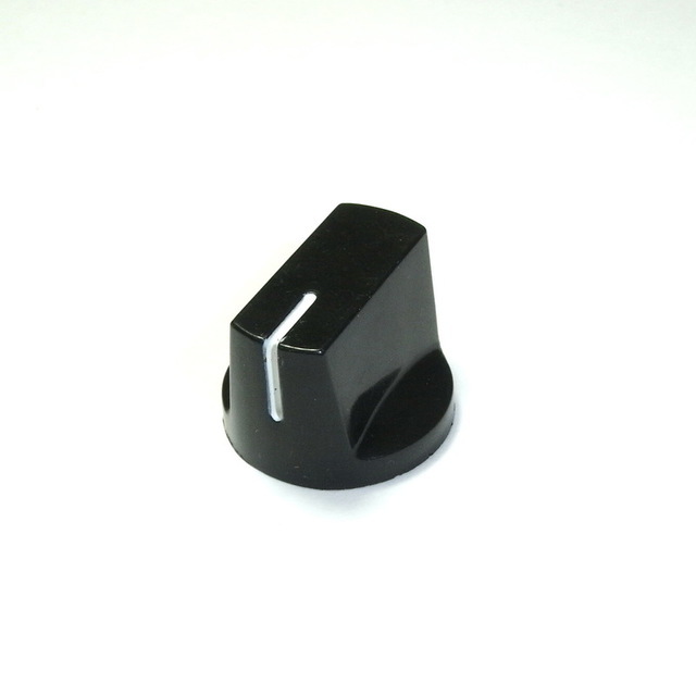
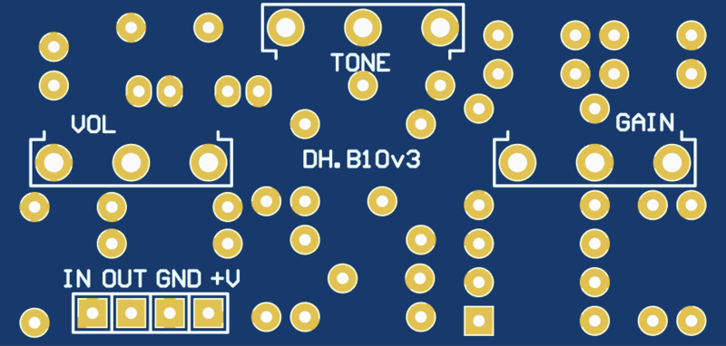
Potentiometers
GAIN 500k-A 500K OHM LOG POTENTIOMETER
VOL 500k-A 500K OHM LOG POTENTIOMETER
TONE 5k-A 5K OHM LOG POTENTIOMETER
PCB SCHEMATIC
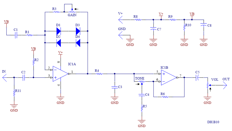
PCB
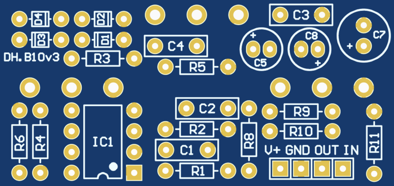
MODIFICATIONS
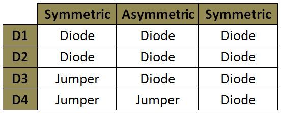
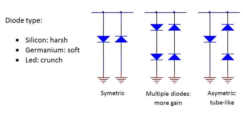
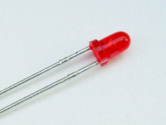
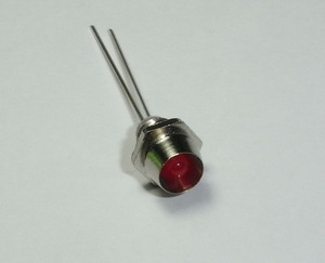
Customize the distortion by swapping the clipping diodes. Germanium diodes (e.g., 1N60, 1N270, 1N34A) deliver a softer distortion, while silicon diodes (e.g., 1N914, 1N4148) provide a harder distortion, and LEDs yield the most aggressive clipping, adding fuzz and crunch. You can experiment with both symmetric and asymmetric configurations. The circuit is originally set to asymmetric; to switch to a symmetric configuration, simply remove the jumper and install a diode in position D4.