Dr Q Autowah
Dr Q is a classic autowah DIY project. This envelope filter effect is highly interactive with the dynamics of the input signal, creating a distinctive choppy rhythm guitar similar to the funk recordings from the 1970s.Steps
Categories
Status: Active

General description of components Step 3 of 6
GENERAL DESCRIPTION OF COMPONENTS
Resistors
Use a multimeter or the color bands to obtain the resistance value. Resistors do not have polarity, you can place them in any direction.

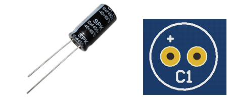
Electrolytic capacitors
Electrolytic capacitors have their value printed on them. The negative polarity pin is indicated by a white strip along the can. They also have a longer leg indicating the positive pin. The maximum voltage rating never can be exceeded, make sure you are using at least double voltage rating than your power supply. For example, if you are using a 9V power supply, use a electrolytic capacitor with at least 18V maximum voltage rating.
Polyester capacitors
Polyester capacitors have their value marked with three numbers. Read as picofarads (pF), the first two are the 1st and 2nd digits and the third is the multiplier code. These capacitors do not have polarity, you can place them in any direction.
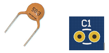
Ceramic capacitors
Ceramic capacitors have their value marked with three numbers. Read as picofarads (pF), the first two are the 1st and 2nd digits and the third is the multiplier code. These capacitors do not have polarity, you can assemble them in any direction.
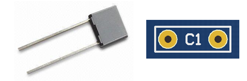
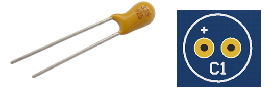
Tantalum capacitors
Tantalum capacitors have the value printed on them. The polarity is marked for the positive pin. Additionally, the longer leg is the positive and shorter the negative. Assemble the tantalum capacitor according to the positive polarity (+) marked on the PCB.
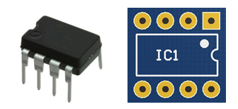
Integrated Circuits
Integrated Circuits (ICs) have their model printed on them. A notch half-circle or a dot indicates the correct position on the PCB.
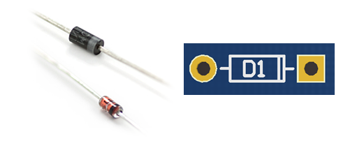
Diodes
Diodes have their model printed on them. The polarity (cathode) is indicated by the ring near the side. This ring is also marked on the PCB.
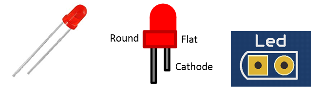
Led diodes
Led diodes have polarity, the cathode is indicated as a flat surface on the side of the diode and also it is the shorter led. On the PCB, the cathode is marked as a flat side and anode as a round side.
Transistors
Transistors are three terminals components and their model is printed on them. To indicate the correct orientation, one side of the transistor is flat and the other one is round.
![]()
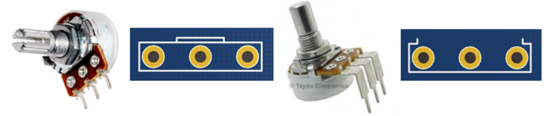
Potentiometers
Potentiometers have their resistance value marked on them. They are marked with A, B or C for logarithmic, linear and reverse logarithmic, respectively.
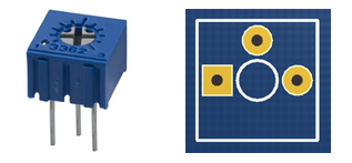
Trimpots
Trimpots are similar to potentiometers. Their values are printed on them. Use a small screwdriver to adjust them.