Bazz Fuzz
The Bazz Fuzz is a very popular project known for its simple, minimal circuit and aggressive, fuzz sound. It's perfect for both guitar and bass.Steps
Categories
Created by DHEA
Status: Active
Status: Active

Designators and components Step 2 of 5
COMPONENT LIST
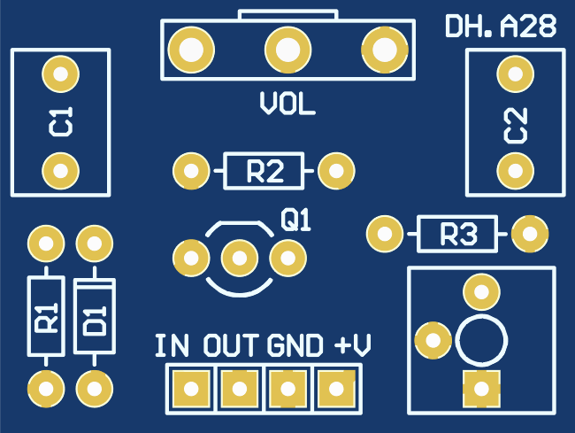
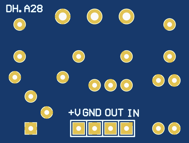
PCB
PCB BAZZ FUZZ PCB
Resistors
R1 1M 1M OHM 1/4W 1% METAL FILM RESISTOR
R2 100k 100K OHM 1/4W 1% METAL FILM RESISTOR
R3 Jumper
Capacitors
C1 4.7u 4.7UF 50V ELECTROLYTIC CAPACITOR 5X11MM
C2 100n 100NF 100V 5% POLYESTER FILM BOX TYPE CAPACITOR
Diode
D1 1N914 1N914 SIGNAL DIODE
Transistor
Q1 2N5088 2N5088 GERENAL PURPOSE TRANSISTOR
Potentiometer
VOL 100k-A 100K OHM LOGARITHMIC POTENTIOMETER
PCB
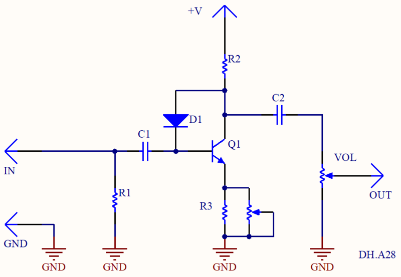
SCHEMATIC
MODS
This PCB is designed for multiple modifications, allowing you to customize the sound.
- Gain control: for adjustable gain, use a 5K TRIMMER on GAIN pad. Alternatively, you can use a fixed resistor at position R3.
- Diode: mount 1N34A for more fuzz, LED for more pronounced distortion.
- Transistor: mount a darlinton transistor MPSA13 on Q1 and a 10K RESISTOR on R2. Always double-check transistors pinout before soldering.
- Input capacitor C1: increase the value of C1 to boost the bass frequencies before the clipping stage.
- Output capacitor C2: increase the value of C2 to boost the bass frequencies after the clipping stage.
Check Homewrecker website for more info and modifications.