Arduino Based Memory Game - PCB
A Simon-says type game that can be easily made from scratch with a few parts and an ArduinoSteps
Categories
Status: Active

Soldering the Circuit Step 4 of 5
The following image shows how I soldered the circuit on my perf board:
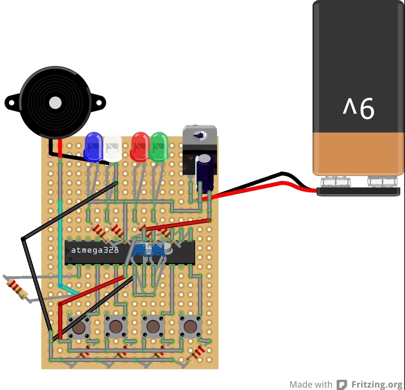
As you can see, I tried to use as little wire as possible to improve the asthetics of the project. The grey lines represent solder beads, while the colored lines are wires. You can either use my soldering as a guide or chose your own way to arrange the componets using the circuit diagram on the previous page.
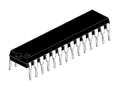
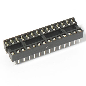
Important: Although this diagram shows the ATMega chip directly soldered onto the board, this is not a true representation. Solder the DIP socket in its place and plug the ATMega chip into this socket once it is programmed (see next step for programming the chip). This protects the ATMega chip from the heat of the soldering iron and allows you to reprogram the chip if you want to make modifications after the fact.
Since it is hard to show all of the solder connections in an image, you can also download the schematic in the attachments or here: https://github.com/jerwil/Simon_Solder/blob/master/simon_solder.fzz
This file can be opened by Fritzing, a great free open-source circuit editor available for download here: http://fritzing.org/download/